[8]
‐
2
2. Outline of customized input/output mode
(A to E below correspond to A to E on the previous page.)
(1)
Customizing the input signal
A.
The ON/OFF signal input from the input port passes through the input control section (no operation, alternate
operation, signal reversal), and is then stored in the physical input area corresponding to the input port.
(Refer to
page [8] - 3)
B.
Each signal stored in the physical input area is connected to a desired position in the sewing machine control
virtual input port.
(Refer to page [8] - 2)
C
. The sewing machine carries out control based on the function assigned to the virtual input area.
(2)
Customizing the output signal
D.
As opposed to the customized input, the virtual output area port, assigned the function, can be connected and
set to a desired position in the physical output area port.
(Refer to page [8] - 2)
E.
The signal for each port in the physical output area passes through the output control section
(no operation, delay circuit, alternate, etc.), and is then output to the output port.
(Refer to page [8] - 4)
3. Customizing the virtual input/output
Selection and connection of physical input/output port and virtual input/output port
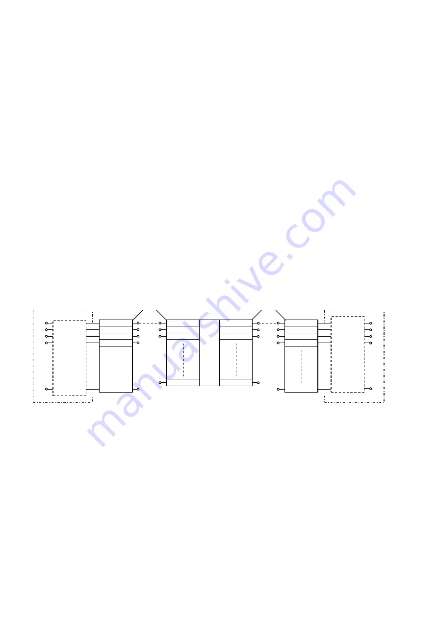
For example, to connect the physical input port [I1] and virtual input port [SRT] (start) and to connect the physical
output port [O1] and virtual output port [T] as shown in the diagram, set as follows.
1. Using customized input, select the [I1] input functions, and set SRT.
2. Using customized output, select the [O1] input functions, and set SRT.
With the above settings, [I1] and [SRT], and [O1] and [T] will be connected.
One port from the virtual input ports can be selected for the [I*] port by changing the setting.
One port from the virtual output ports can be selected for the [O*] port by changing the setting.
Customized
output
I1
I2
I3
I4
SRT
IF1
NO
T
W
L
O1
O2
O3
O4
Customized
input
Physical
input
Physical
output
Input control
section
Output control
section
A
lt
e
rn
a
te
In
p
u
t
re
v
e
rs
a
l
A
lt
e
rn
a
te
o
u
tp
u
t
re
v
e
rs
a
l
ON
/OFF
d
e
lay
c
h
o
p
p
ing
S
e
w
ing
ma
c
h
ine
c
o
n
tr
o
l
Virtual
input
Virtual
output
Summary of Contents for PLK-J-CU-20S
Page 1: ...INDUSTRIAL SEWING MACHINE MODEL PLK J CU 20S TECHNICAL MANUAL Control Unit A180E816P01 ...
Page 38: ... 12 Several power supply 1 3Ø AC200V 240V 50 60Hz 2 1Ø AC200V 240V 50 60Hz Except Europe 12 1 ...
Page 39: ...3 3Ø AC380V 415V 50 60Hz Except Europe 4 1Ø AC200V 240V 50 60Hz Europe 12 2 ...
Page 53: ......
Page 54: ......
Page 55: ......
Page 56: ...Printed in Japan ...


