[8]
‐
3
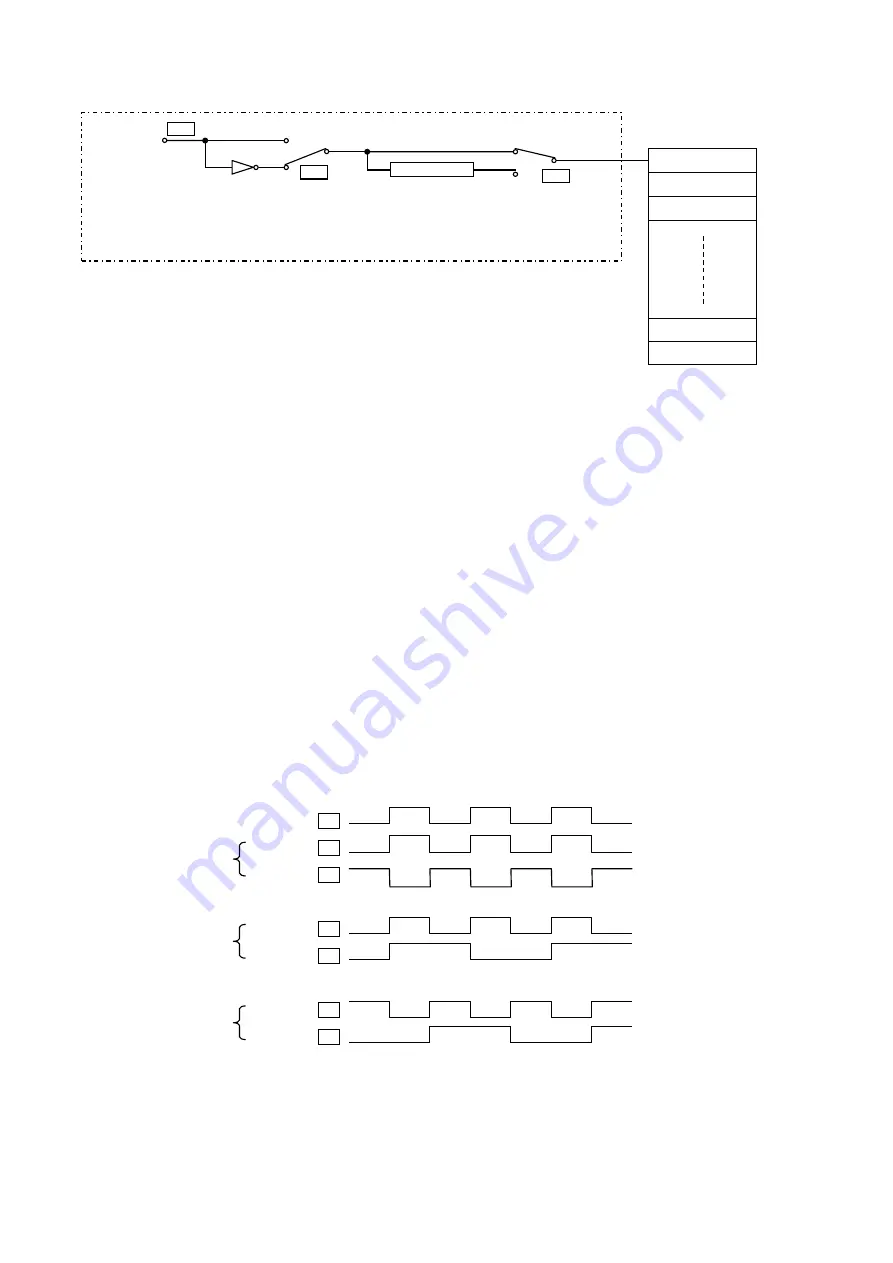
4. Block diagram (input control section)
Standard
Logic changeover
Operation changeover
5. Explanation of operations (input control section)
The input signal passes through the A point, B point and C point of the input port, and finally is connected to the
physical input
A point
Inputs the signal to the input port from an external source.
B point
(1) When the logic setting is set to "normal"(OF), the operation will be the same as the input signal
A point.
(2) When the logic setting is set to "reverse"(ON), the operation will be the reverse of the input signal
A point.
C point
(1) When the operation selection is set to "normal"(NO), the operation will be the same as the input
signal B point.
(2) When the operation selection is set to "alternate"(AL), the signal will turn ON at the first rising edge,
turn OFF at the second rising edge, and will turn ON at the third rising edge. The signal waveform
will repeatedly turn ON and OFF at the input rising edge.
The C point signal input and controlled in the above manner is input into the physical input port.
Input port
A
“Normal”
B
"Reverse"
B
“Normal”
C
"Alternate" C
“Normal”
C
"Alternate" C
OF
ON
Alternate
NO
AL
A
C
B
Logic
changeove
r
Logic operation
selection when
logic changeover
is set to "normal"
Logic operation
selection when logic
changeover is set to
"reverse"
Physical input
Summary of Contents for PLK-J-CU-20S
Page 1: ...INDUSTRIAL SEWING MACHINE MODEL PLK J CU 20S TECHNICAL MANUAL Control Unit A180E816P01 ...
Page 38: ... 12 Several power supply 1 3Ø AC200V 240V 50 60Hz 2 1Ø AC200V 240V 50 60Hz Except Europe 12 1 ...
Page 39: ...3 3Ø AC380V 415V 50 60Hz Except Europe 4 1Ø AC200V 240V 50 60Hz Europe 12 2 ...
Page 53: ......
Page 54: ......
Page 55: ......
Page 56: ...Printed in Japan ...


