–27–
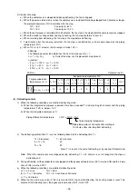
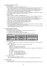
OFF
ON
1 2 3 4 5 6
OFF
ON
1 2 3 4 5 6
OFF
ON
1 2 3 4 5 6
OFF
ON
1 2 3 4 5 6
OFF
ON
1 2 3 4 5 6
OFF
ON
1 2 3 4 5 6
OFF
ON
1 2 3 4 5 6
OFF
ON
1 2 3 4 5 6
OFF
ON
1 2 3 4 5 6
OFF
ON
1 2 3 4 5 6
OFF
ON
1 2 3 4 5 6
OFF
ON
1 2 3 4 5 6
OFF
ON
1 2 3 4 5 6
OFF
ON
1 2 3 4 5 6
OFF
ON
1 2 3 4 5 6
OFF
ON
1 2 3 4 5 6
0
1
2
3
4
5
6
7
8
9
10
11
12
13
14
15
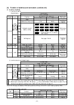
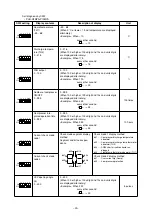
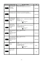
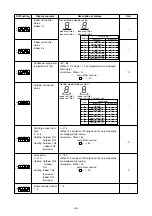
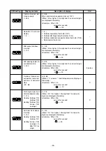
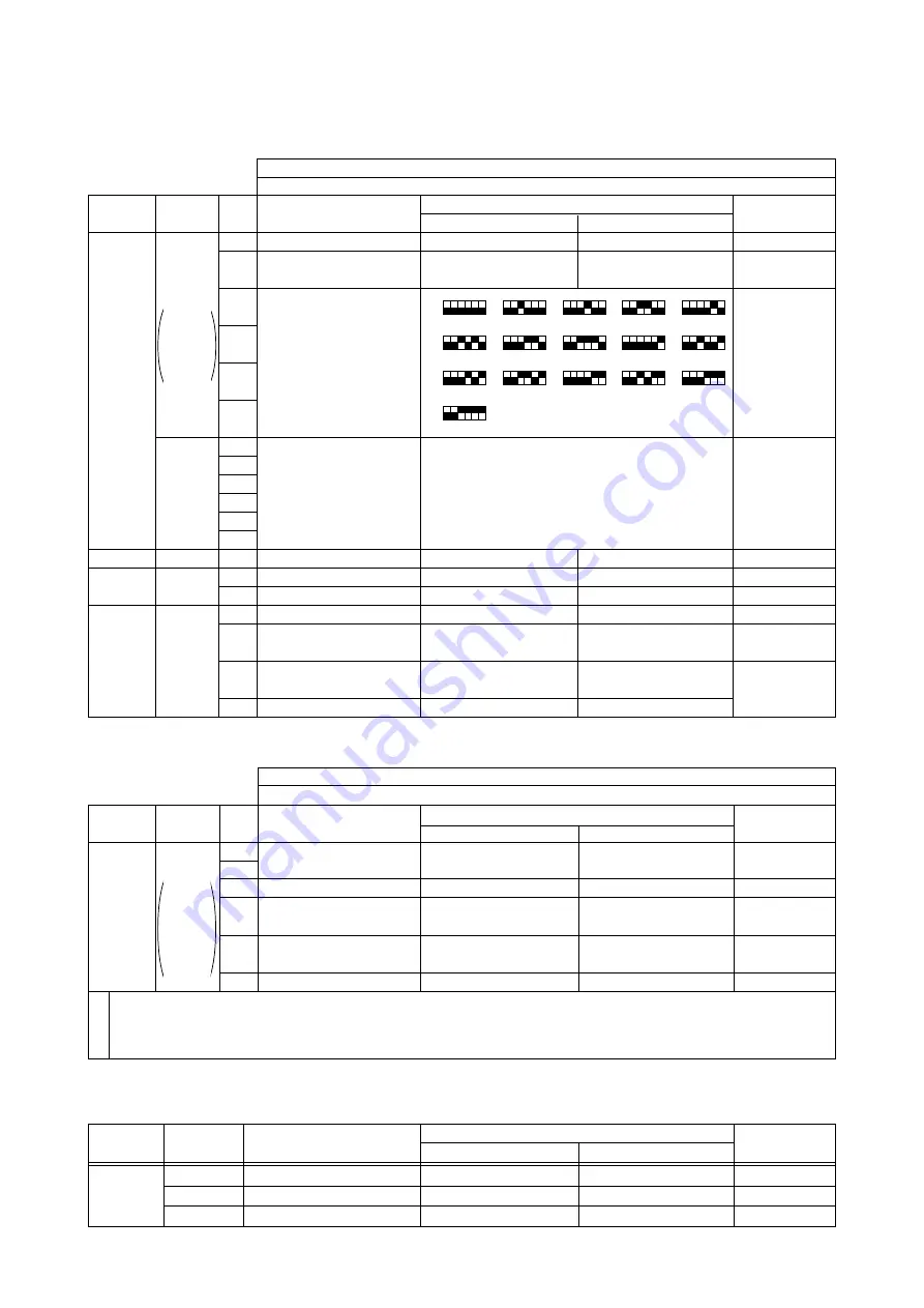
[3] Function of switches and connectors (outdoor unit)
(1) Function of switches
1) Function of switches
(Normal mode)
Switch
SW1
CN33
When
open
(Normal)
SW2
SW3
SW4
SW5
Switch effec-
tive timing
–
Running or
stopped
When power
turned on
Running or
stopped
stopped
stopped*
1
stopped
–
When power
turned on
When power
turned on
Operation by switch operation
ON
OFF
–
–
Clear
Normal
See pages 29 to 34.
Register
Normal
Operate
Stop
Heat
Cool
Do
Do not
Do not
Do
Cooling only
Heat pump
PUH-P10MYA
PUH-P8MYA
Normal mode
SW3 = Unrelated
Kind of
switch
DIP SW
Tact SW
DIP SW
DIP SW
Pole
1
2
3
4
5
6
1
2
3
4
5
6
1
2
1
2
3
4
Function
None
Abnormality history clear
Refrigerant system
address setting
Self diagnosis
Mode input register
Trial run
Trial run mode switching
Inlet temp. re-reading
3-phase power source
detection
Cooling only switching
Model setting
Remarks
Function
None
Night mode
Defrosting end switching
Defrosting prohibit time
switching
None
Switch effec-
tive timing
–
stopped
stopped
stopped
–
Switch
SW1
When
CN33
shorted
(mode
switching)
Operation by switch operation
ON
OFF
–
–
Night mode
Normal mode
Fixed
Training
–
–
Kind of
switch
DIP SW
Pole
1
2
3
4
5
6
*1 Trial run performs trail run processing by input change while stopped. (For details, see the trail run section)
*2 Mode input is entered by SW3 OFF
→
ON change (___
↑
). Press and hold down SW3 for about 2 seconds. The set
mode can be registered according to the outdoor unit setting information on page 31.
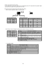
2) Switch functions at set mode change
Note: After changing the mode by CN33 shorting (mode switching), return to the normal mode by opening CN33.
3) Connector function assignment
12
°
C continuous 2 min-
utes
8
°
C continuous 2 min-
utes
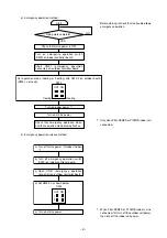
Set input mode
CN33 = short SW3 = ON*
2
→
Shows that Nos. 3, 4, 5 , and 6 of
SW1 are ON.
Type
Connector
Connector
CN31
CN32
CN33
Function
Emergency operation
Function test
DIP switch mode switching
Operation by open/short
short
open
Start
Normal
Function mode
Normal
Mode switching
Normal
Switch effec-
tive timing
At initialization
At initialization
stopped

