–38–
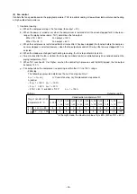
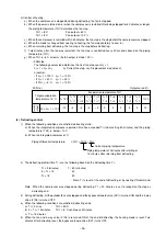
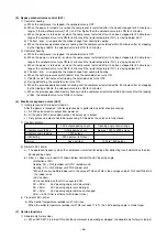
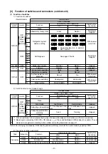
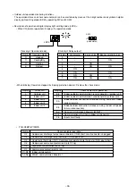
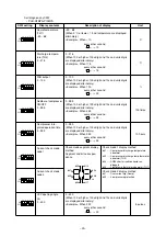
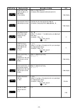
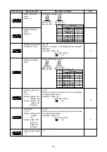
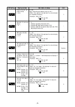
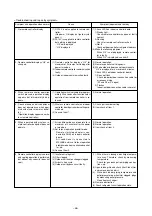
2) Judgment method and probable trouble mode
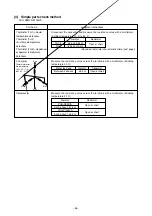
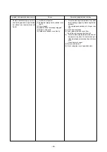
3) Electronic expansion valve motor replacement instructions
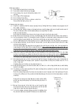
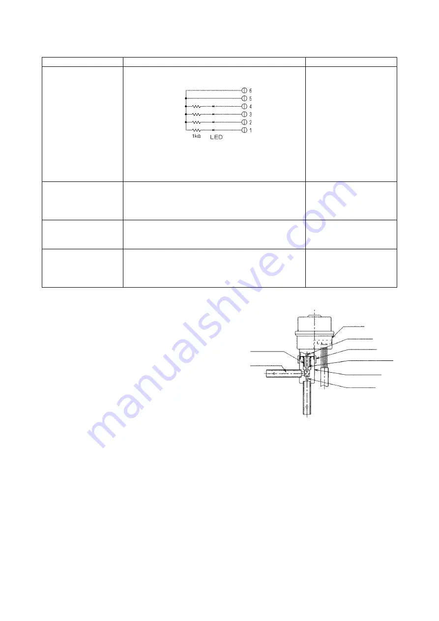
1. Description of construction
1.1 A lock nut connects the motor to the valve body.
1.2 The motor consists of a motor rotating section, rotation
transmission gear section, and a driver which converts
rotation to linear motion.
1.3 The valve body consists of a valve assembly, which
moves up and down, and an orifice.
A bellows at the top of the valve body block isolates the
refrigerant circuit from the atmosphere side.
Therefore, the motor is not exposed to the refrigerant.
2. Principle of operation
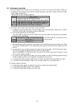
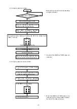
2.1 Pulses output from the control circuit board are sequentially supplied to four coils and the motor is rotated.
The motor can be rotated in either clockwise or counterclockwise by changing the order in which the pulses are
supplied.
2.2 The gear section reduces the motor speed to 1/30 and supplies the motor rotation to the motor output shaft.
2.3 The motor output shaft is threaded and is used as a driver.
2.4 The up and down motion of the end of the driver moves the valve assembly of the valve body up and down and
controls the flow by changing the distance between the orifice and the bottom end of the valve.
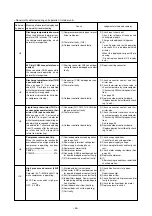
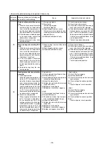
Trouble mode
Microcomputer drive cir-
cuit faulty
LEV mechanism locked
LEV motor coil open or
shorted
Connector connection in-
correct, or contact faulty
Judgment method
(1) Disconnect the control circuit board connector, and con-
nect the check LED shown below.
When the mains power is turned on, a pulse signal is out-
put for 10 seconds.
If the LED remains OFF or ON, the drive circuit is abnor-
mal.
(1) When the LEV is in the locked state and driven, the mo-
tor races. At this time, a soft clicking sound is generated.
When this sound is generated both when closing and
when opening, the mechanism is abnormal.
Measure the resistance between the coils (red-white, red-
orange, brown-yellow, brown-blue) with a multimeter.
If 150
Ω ±
10 %, the coil is normal.
(1) Visually check for loose connector terminals and check
the color of the lead wires.
(2) Disconnect the control circuit board connector and
check the continuity with a multimeter.
Remedy
When drive circuit is faulty, re-
place control circuit board.
Replace LEV
Replace LEV coil
Check continuity of faulty point
Valve assembly
Motor
Driver
Lock nut
Refrigerant
circuit
Valve body
Orifice
Bellows

