95
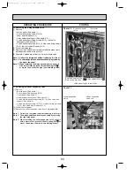
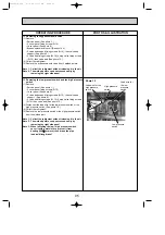
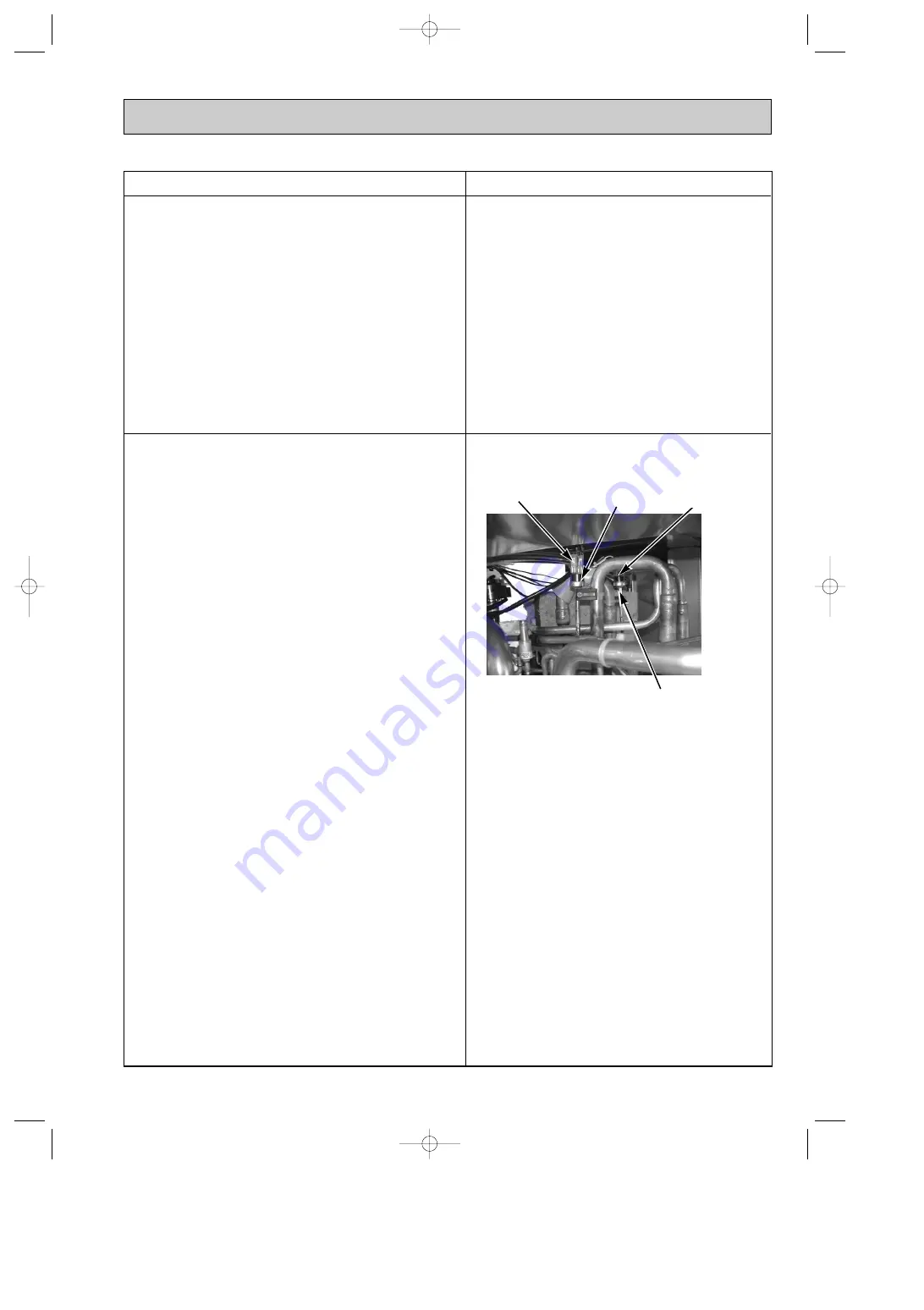
Photo 12
Lead wire for the
high pressure
switch
High pressure
switch
Lead wire for
the low
pressure
switch
Low pressure
switch
OPERATING PROCEDURE
PHOTOS & ILLUSTRATION
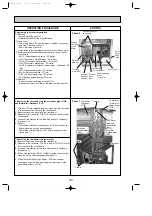
12. Removing the bypass solenoid valve
(1) Remove
• Service panel (See photo 1.)
• 3 cover panel fixing screws (5
o
10)
• Cover panel (See photo 6.)
• Bypass solenoid valve coil (See photo 9.)
• 2 valve bed support fixing screws (5
o
10), then valve bed
support (See photo 9.)
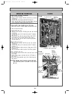
• 4 valve bed fixing screws (5
o
10), 4 stop valve fixing screws
(5
o
16), then valve bed (See photo 15.)
(2) Collect the refrigerant.
(3) Remove the bypass solenoid valve from 2 welded points.
Note 1: Collect the refrigerant without releasing it in the air.
Note 2: The welded points can be accessed easily by
removing the right side panel.
13. Removing the low pressure switch and the high pressure
switch
(1) Remove
• Service panel (See photo 1.)
• 3 cover panel fixing screws (5
o
10)
• Cover panel (See photo 6.)
• 2 valve bed support fixing screws (5
o
10), then valve bed
support (See photo 9.)
• 4 valve bed fixing screws (5
o
10), 4 stop valve fixing screws
(5
o
16), then valve bed (See photo 15.)
(3) Disconnect the lead wire for the low pressure switch or the
high pressure switch. (See photo 12.)
(4) Collect the refrigerant.
(5) Remove the low pressure switch or the high pressure switch
from the welded part.
Note 1: Collect the refrigerant without releasing it in the air.
Note 2: The welded points can be accessed easily by
removing the right side panel.
Note 3: When installing the low / high pressure switch,
cover it with a wet cloth to prevent it from
heating (100
;
;
or more), then braze the pipe
(non-oxidizing braze).
OC338C-4.qxp 07.5.24 11:27 AM Page 95

