97
OPERATING PROCEDURE
PHOTOS
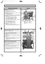
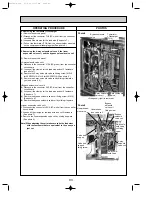
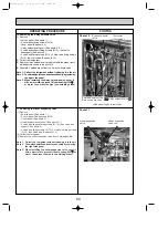
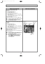
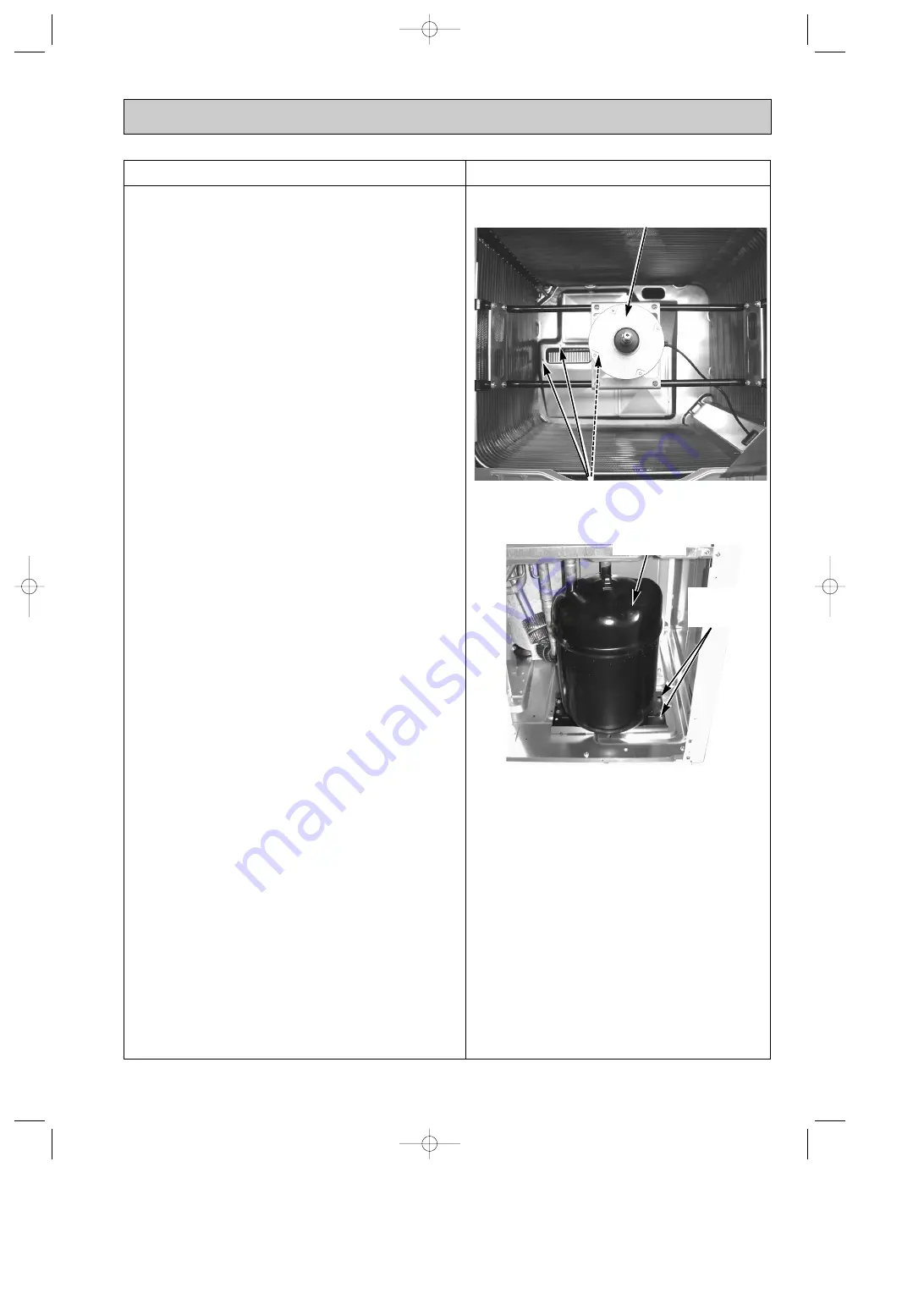
Photo 17
Photo 16
16. Removing the accumulator
(1) Remove
• Service panel (See photo 1.)
• Electrical parts box (See photo 6.)
• 2 electrical parts box leg fixing screws (5
o
10), then electrical
parts box legs (See photo 6.)
• 2 lower fixing screws (5
o
10) of the heatsink duct
• 2 screws (4
o
10) which hold the metal plate above the
heatsink, then remove the plate
• Fan guard
• 3 upper fixing screws (5
o
10) of the heatsink duct located
below the fan motor, then remove the hearsink duct (See
photo 16.)
(2) Collect the refrigerant.
(3) Disengage 2 welded points of the accumulator inlet and outlet.
(See photo 17.)
(4) Remove 4 accumulator fixing screws (5
o
10), then take out the
accumulator.
Note 1: Collect the refrigerant without releasing in the air.
Note 2: The welded points can be accessed easily by remov-
ing the rear panel. When servicing from the rear side,
remove the rear panel first, then follow the procedure
from (2) mentioned above.
Fan motor
Upper heat sink duct fixing screw (3pcs)
Accumulator
Accumulator
fixing screw
(4pcs)
<Viewed from rear side>
OC338C-4.qxp 07.5.24 11:27 AM Page 97

