background image

52

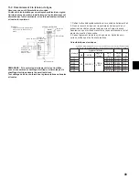
13.5. Ventilation avec récupération d’énergie (ERV)

6pTXHQFHGHIRQFWLRQQHPHQW

/¶LQWHUUXSWHXUGHODGHPDQGH(59IHUPH&1(5

9&&HVWIRXUQLj&1&SRXUDFWLYHUODYHQWLODWLRQDYHFUpFXSpUDWLRQG¶pQHUJLH

6LO¶DSSDUHLOSDVVHHQGpJLYUDJH&1&DUUrWHODVRUWLHGH9&&

,QWHUUXSWHXU(59
(QWUpHGXFRQWDFW$VDQVWHQVLRQ
7HQVLRQQRPLQDOHGXFRQWDFW! 9&&
&RXUDQWQRPLQDOGXFRQWDFW! $
&KDUJHPLQLPDOHDSSOLFDEOH P$HQ&&

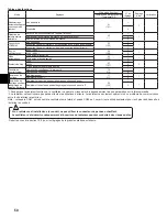
Sortie ERV

Condition

Vitesse de ventilation

Sortie CN2C 

(= Sortie du ventilateur)

Entrée CNER

OFF

Opération de 

refroidissement/

FKDXIIDJHYHQWLODWLRQ

Réglage RC

21

'pJLYUDJH

ARRÊT

OFF

ARRÊT

ARRÊT

OFF

21

Opération de 

refroidissement/

FKDXIIDJHYHQWLODWLRQ

Réglage RC

21

'pJLYUDJH

ARRÊT

OFF

ARRÊT

ARRÊT

21

5&&RPPDQGHjGLVWDQFH

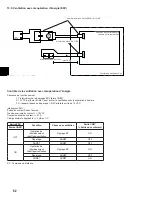
Contrôle de la ventilation avec récupération d’énergie

1XPpURGHSLqFH&15(/$<.,7&0

3DQQHDXGHFRQWU{OHGDQVOD

FHQWUDOHGHWUDLWHPHQWG¶DLU

Centrale de traitement d’air

max 30 ft.

,QWHUUXSWHXU(59VXUVLWH

%RELQH


12 VCC

1XPpURGHSLqFH3$&

Summary of Contents for PVA-A12AA7

Page 1: ... installation manual thoroughly before installing the air conditioner unit FOR INSTALLER P SERIES MANUEL D INSTALLATION Veuillez lire le manuel d installation en entier avant d installer ce climatiseur pour éviter tout accident et vous assurer d une utilisation correcte POUR L INSTALLATEUR English Français ...

Page 2: ... the unit 7 8 Duct connection 7 9 Mount positions 8 9 1 Vertical installations 8 9 2 Horizontal right installations 9 9 3 Horizontal left installations 10 RZQÀRZ LQVWDOODWLRQV 14 LU OWHU 16 11 Refrigerant piping work 17 11 1 Insulation 18 11 2 Piping size 18 12 Drain connections 19 13 Electrical wiring 20 13 1 Remote controllers 21 13 2 Connecting line voltage 22 RQGHQVDWH RYHUÀRZ VDIHW VZLWFK FRQ...

Page 3: ...tion ø26 Knockout Hole Remote controller transmission ø26 Knockout Hole ø26 Knockout Hole ø26 Knockout Hole Indoor Outdoor unit connection Indoor Outdoor unit connection Remote controller transmission Note 1 Keep the service space for maintenance at the front Unit mm in Top Top view Front Bottom Bottom view view Left side view Right side view 3 3 2 1 Unit mm in Model A B C D E F G H J MGas Pipe NL...

Page 4: ...nstalling and moving the air conditioner to another site do not charge it with a refrigerant different IURP WKH UHIULJHUDQW VSHFL HG RQ WKH XQLW If a different refrigerant or air is mixed with the original refrigerant the refrigerant cycle may malfunction and the unit may be damaged x When moving and reinstalling the air conditioner consult the dealer or an authorized technician If the air conditi...

Page 5: ...rmance may drop x Do not use a refrigerant other than R410A If another refrigerant is used the chlorine in the refrigerant may cause the refrigerator oil to deteriorate x 8VH D YDFXXP SXPS ZLWK D UHYHUVH ÀRZ FKHFN YDOYH 7KH YDFXXP SXPS RLO PD ÀRZ EDFN LQWR WKH UHIULJHUDQW cycle and cause the refrigerator oil to deteriorate x Do not use the following tools that are used with conventional refrigeran...

Page 6: ...nds for packaging Do not use any PP bands for a means of transportation it is dangerous R QRW WRXFK WKH KHDW H FKDQJHU QV RLQJ VR PD FXW RXU QJHUV x Safely dispose of the packing materials Packing materials such as nails and other metal or wooden parts may cause stabs or other injuries Tear apart and throw away plastic packaging bags so that children will not play with them If children play with a...

Page 7: ... Left DQG RZQÀRZ FRQ JXUDWLRQ DV VKRZQ LQ VWHS WKURXJK The units are designed for 0 zero clearance to combustibles 24 is required for service access to the front of the unit See Installation OHDUDQFH 5HJDUGOHVV RI PRXQWLQJ FRQ JXUDWLRQ WKH DLU KDQGOHU must be mounted level to facilitate proper condensate drainage Installation Clearance TOP View Horizontal Installation 24 24 Width of Unit TOP View ...

Page 8: ...nd PVA A18 only Dual side returns must be used on all other models to ensure SURSHU DLU ÀRZ I WKH VLGH UHWXUQ LV XVHG it is the responsibility of the installer to ensure the ducts are properly sized and sealed to the cabinet When cutting in to the side of the cabinet use the provided dimples to avoid damaging any internal structure or wiring PLENUM DUAL SIDE RETURN SEAL BOTTOM OF AIR HANDLER ADD T...

Page 9: ...g of the plastic tube is required please refer to the table for length Finally secure the clear plastic tubes to the top drain pan per Detail A Then to the metal brackets supporting the coil to the top drain pan with the provided plastic ties as shown Model Tube Length PVA A12 A18 4 9 in 125 mm PVA A24 30 6 9 in 175 mm PVA A36 42 8 9 in 225 mm Tube length provided Reinstall the coil assembly along...

Page 10: ...bag will also need to be attached to the top drain pan See instructions below Directions for rotating fan for Horizontal Left Installation Step 1 Remove the panel marked FILTER Step 2 Remove the panel marked BLOWER Step 3 Remove the panel marked ELECTRICAL Step 4a Remove the screws securing the 3 panels to the COIL panel shown in the image above Remove the 1st panel and 2nd panel marked COIL Step ...

Page 11: ...inal location Step 11 Reinsert the blower assembly with the motor now on the left into the air handler cabinet and reuse the 2 screws that secured the fan assembly in position Reroute the 2 connectors for the motor back into the enclosure and reconnect NOTE The wiring harness might have to be removed from the plastic retainers mounted to the motor bracket in order to have VXI FLHQW OHQJWK WR UHDFK...

Page 12: ...ith supporting brackets 4 screws from the coil assembly A B PLATE GUIDE REAR SIDE DRAIN PAN C DETAIL B DETAIL B Step 14a Install the 2 drain pan seals included in the accessory bag as shown above These seals will cover the unused holes in the side drain pan to prevent leaks DETAIL B Step 14b Reinstall the brackets to the opposite side of the Side Drain Pan The Side Drain Pan will be reinstalled on...

Page 13: ...mistor connector will also reroute into the electrical section and plug into CN44 Refer to 9 3 Step 1 to 4 in reverse order to reassemble the panels Ensure the proper knockouts are removed for drainage and electrical connections NOTE For Horizontal installation an auxiliary drain pan must be installed Auxiliary drain pan MOTOR ON BOTTOM SIDE DRAIN PAN ON BOTTOM REATTACH BRACKETS PRIMARY DRAIN 3 4 ...

Page 14: ...efer to 9 3 Steps 1 to 4 for removing the panels which cover the Electrical Coil Assembly Blower and Filter Step 2 A Unplug the Thermistor CN44 from the control board and route the harness from control box area out through the rubber grommet B Remove the brackets which secure the coil assembly if not already done C Slide the coil assembly out of the air handler cabinet Step 3 Rotate the cabinet so...

Page 15: ...istor CN44 to the control board Step 4c In order to prevent water from running down the Thermistor wires into the electrical area a Drip Loop MUST be installed to direct water into the drain pan 3rd 1st 2nd METAL TAB BEND AROUND THE WIRE HARNESS DRIP LOOP TO ELECTRICAL SECTION DETAIL A INSIDE DRAIN PAN Step 5 Reinstall the panels over the drains and refrigerant lines Next install the panels which ...

Page 16: ... Mounting Platform Mounting LU OWHU ZDVKDEOH UHXVDEOH DLU OWHU LV SURYLGHG ZLWK WKH DLU KDQGOHU XQLW 7KH OWHU FDQ EH LQVWDOOHG RQFH WKH XQLW KDV EHHQ UHPRYHG IURP LWV SDFNDJLQJ W LV UHFRPPHQGHG WKH DLU OWHU EH FOHDQHG RQFH SHU month The pressure drop is to be determined by the installing contractor based on the overall static pressure performance of the system including supply and return ductwork ...

Page 17: ...I WKH HQG RI WKH SLSH WR UHOHDVH DQ gas Both refrigerant lines need to be insulated all the way up to the cabinet Make sure the openings in the cabinet around the refrigerant lines are sealed 3 8 in thick insulation is the minimum recommended thickness Based on ambient conditions local codes and line length thicker insulation may be desired R QRW SXW DQ RLO RQ WKH WKUHDGHG SRUWLRQ RI WKH ÀDUH QXWV...

Page 18: ... a minimum density of 0 03 and D WKLFNQHVV DV VSHFL HG LQ WKH WDEOH EHORZ Pipe size Insulation thickness 6 4 mm to 25 4 mm 1 4 to 1 in 10 mm 7 16 in 28 6 mm to 38 1 mm 1 1 8 to 1 1 2 in 15 mm 5 8 in If the unit is used on the highest story of a building and under high temperature and high humidity it is necessary to use thicker insulation WKDQ VSHFL HG LQ WKH WDEOH DERYH I WKHUH DUH FXVWRPHU V VSH...

Page 19: ... sweating could cause water damage Upon completion of installation it is the responsibility of the installer to ensure the drain pan s captures all condensate and all condensate is draining properly and not getting into the ductwork system Vertical Mounting When mounted vertically the air handler s primary drain connection is located in the center of the unit The slightly higher drain to the left ...

Page 20: ...r to the power Install the unit to prevent that any of the control circuit cables remote controller transmission cables is brought in direct contact with the power cable outside the unit Ensure that there is no slack on all wire connections Some cables power remote controller transmission cables above the ceiling may be bitten by mouses Use as many metal pipes as possible to insert the cables into...

Page 21: ... wiring is complete make sure again that there is no tension on the connections and attach the cover onto the control box in the reverse order removal Also seal any openings created from wiring into the air handler This will prevent air leakage Caution Wire the power supply so that no tension is imparted Otherwise GLVFRQQHFWLRQ KHDWLQJ RU UH PD UHVXOW Important Attach shielding ground on the outdo...

Page 22: ...frost and Error 23 123 1 1 Enable heater and fan during Defrost and Error 2 2 1 While the heater is on the fan will operate at high speed regardless of the fan setting on the remote controller 2 Heater will not operate during all error modes Heater will only operate during a communication error between indoor unit and outdoor unit Note When CN4Y is used the fan is off when CN24 is energized which ...

Page 23: ...andler will be set to 0 50 ESP from the factory The air handler s static pressure can be changed through the mode function settings in the controller Please refer to the installation manual for the controller on how to change this option Depending on the controller used the mode function will be either 08 for mode PAR 31 Simple MA or 108 for function MHK1 Please notice there are different settings...

Page 24: ...V Switch Non Voltage a contact input Contact rating voltage 15VDC Contact rating current 0 1 A Minimum applicable load 1mA at DC ERV output Condition Fan speed CN2C output Fan output CNER input OFF Cool Heat Fan operation RC setting ON Defrost STOP OFF STOP STOP OFF ON Cool Heat Fan operation RC setting ON Defrost STOP OFF STOP STOP ON RC Remote controller ERV Control max 30 ft Part Number PAC 740...

Page 25: ...ltage 15VDC Contact Rating Current 0 1 A Minimum Applicable Load 1mA at DC Mode No Humidistat Output Condition No Defrost No Error CN25 Output Fan Speed 16 CNF Input 1 OFF Heat operation Thermo OFF OFF RC setting Heat operation Thermo ON ON Heat operation Thermo OFF OFF RC setting Heat operation Thermo ON ON High 2 OFF Heat operation Thermo OFF OFF RC setting Heat operation Thermo ON ON Heat opera...

Page 26: ...sor is warmed up for two to three hours The time necessary to warm up the compressor varies according to atmospheric conditions and refrigerant accumulation To operate the compressor with refrigerant accumulated in the compressor the compressor must be warmed up at least 12 hours to prevent breakdown I WKH LQVXODWLRQ UHVLVWDQFH ULVHV DERYH 0ȍ WKH FRPSUHVVRU LV not faulty Caution x The compressor w...

Page 27: ...rly after the above test run has been performed refer to the following table to remove the cause Symptom Cause Wired remote controller LED 1 2 PCB in outdoor unit PLEASE WAIT For about 2 minutes following power on After LED 1 2 are lighted LED 2 is turned off then only LED 1 is lighted Correct operation For about 2 minutes after power on operation of the remote controller is not possible due to sy...

Page 28: ...ntrolled with the remote controller the operation mode set temperature and the fan speed are memorized by the indoor controller board The auto restart function sets to work the moment the power has restored after power failure then the unit will restart automatically Set the AUTO RESTART FUNCTION using the remote controller Mode no 01 ...

Page 29: ...stallation de l appareil 34 5DFFRUGHPHQW GHV FRQGXLWV 34 9 Positions de montage 35 QVWDOODWLRQ YHUWLFDOH 35 QVWDOODWLRQ KRUL RQWDOH GX F Wp GURLW 36 QVWDOODWLRQ KRUL RQWDOH GX F Wp JDXFKH 37 QVWDOODWLRQ HQ ÀX GHVFHQGDQW 41 LOWUH j DLU 43 0LVH HQ SODFH GHV WX DX GH UpIULJpUDQW 44 11 1 Isolation 45 7DLOOH GHV WX DX 45 5DFFRUGV G pYDFXDWLRQ 46 kEODJH pOHFWULTXH 47 RPPDQGHV j GLVWDQFH 48 5DFFRUGHPHQW ...

Page 30: ...érieur Bornier Transmission de la commande à distance 2 ø4 6 Trous d ébavurage pour l installation du chauffage électrique ø26 Orifice défonçable Transmission de la commande à distance ø26 Orifice défonçable ø26 Orifice défonçable ø26 Orifice défonçable Connexion de l appareil intérieur extérieur Connexion de l appareil intérieur extérieur Transmission de la commande à distance Remarque 1 Conserve...

Page 31: ...lavage etc HOD SRXUUDLW SURYRTXHU XQH pOHFWURFXWLRQ XQ LQFHQGLH RX GH OD IXPpH x Lors du nettoyage de l échangeur thermique et du bac de récupération assurez vous que la boîte de commande le moteur et le LEV restent secs en utilisant une couverture étanche x Lors de l installation et du déplacement du climatiseur vers un autre site ne le chargez pas avec un réfrigérant GLIIpUHQW GH FHOXL TXL HVW V...

Page 32: ...s tuyaux à utiliser pour l installation à l intérieur et laissez les deux extrémités des tuyaux couvertes jusqu au moment du brasage Gardez les tuyaux coudés et autres raccords dans un sac en plastique 6L GH OD SRXVVLqUH GH OD VDOHWp RX GH O HDX V LQ OWUH GDQV OH F FOH GH UpIULJpUDWLRQ OH UpIULJpUDQW ULVTXH GH VH GpWpULRUHU HW OH FRPSUHVVHXU ULVTXH GH QH SDV IRQFWLRQQHU FRUUHFWHPHQW x Utilisez un ...

Page 33: ...nement Précaution x Mettez l appareil sous tension au moins 12 heures avant de le faire fonctionner D PLVH HQ PDUFKH GH O DSSDUHLO LPPpGLDWHPHQW DSUqV VD PLVH VRXV WHQVLRQ SRXUUDLW SURYRTXHU GH VpULHX GpJkWV DX pOpPHQWV LQWHUQHV 1H PHWWH SDV O DSSDUHLO KRUV WHQVLRQ SHQGDQW OD VDLVRQ GH IRQFWLRQQHPHQW x Ne touchez pas les interrupteurs avec les doigts mouillés 7RXFKHU XQ LQWHUUXSWHXU DYHF OHV GRLJW...

Page 34: ...LWHU OH ERQ pFRXOHPHQW GHV FRQGHQVDWV VSDFH QpFHVVDLUH j O LQVWDOODWLRQ TOP View Horizontal Installation 24 24 Width of Unit TOP View Vertical Installation Length of Unit Clearance Area Clearance Area 7 Installation de l appareil 9XH GH 6686 Installation YHUWLFDOH Zone de dégagement 9XH GH 6686 Installation horizontale Zone de dégagement DUJHXU GH l appareil RQJXHXU GH l appareil 0 75 MAX 8 Raccor...

Page 35: ...rWUH XWLOLVpV VXU WRXV OHV DXWUHV PRGqOHV SRXU DVVXUHU OH ERQ pFRXOHPHQW GH O DLU 6L OH UHWRXU ODWpUDO HVW XWLOLVp l installateur est responsable de s assurer que les conduits sont de taille correcte et qu ils VRQW pV GH PDQLqUH pWDQFKH DX FDLVVRQ RUV GH OD GpFRXSH VXU OH F Wp GX FDLVVRQ XWLOLVH OHV HQFRFKHV IRXUQLHV SRXU QH SDV HQGRPPDJHU OD VWUXFWXUH LQWHUQH RX OH FkEODJH PLENUM DUAL SIDE RETURN...

Page 36: ...H GH FRXSHU OHV WXEHV HQ SODVWLTXH UHSRUWH YRXV DX WDEOHDX UHODWLI j OD ORQJXHXU GHV WXEHV Q Q H OHV WXEHV HQ SODVWLTXH WUDQVSDUHQW DX EDF GH UpFXSpUDWLRQ VXSpULHXU FRPPH LQGLTXp SDU OH pWDLO SXLV H OHV DX VXSSRUWV PpWDOOLTXHV GH DWLRQ GH OD ERELQH DX EDF GH UpFXSpUDWLRQ VXSpULHXU j O DLGH GHV VHUUH FkEOHV HQ SODVWLTXH IRXUQLV FRPPH LQGLTXp Modèle Longueur de tube 39 LQ PP 39 LQ PP 39 LQ PP RQJXHX...

Page 37: ...W rWUH pV DX EDF GH UpFXSpUDWLRQ VXSpULHXU 5HSRUWH YRXV DX LQVWUXFWLRQV FL GHVVRXV Instructions concernant la rotation du ventilateur pour une installation horizontale du côté gauche Étape 1 5HWLUH OH SDQQHDX SRUWDQW O LQVFULSWLRQ 7 5 Étape 2 5HWLUH OH SDQQHDX SRUWDQW O LQVFULSWLRQ 2 5 Étape 3 5HWLUH OH SDQQHDX SRUWDQW O LQVFULSWLRQ 75 Étape 4a 5HWLUH OHV YLV GH DWLRQ GHV SDQQHDX DX SDQQHDX 2 FRPP...

Page 38: ...OH EORF YHQWLODWHXU DYHF OH PRWHXU GpVRUPDLV j JDXFKH GDQV OH FDLVVRQ GH OD FHQWUDOH GH WUDLWHPHQW G DLU HW UpXWLOLVH OHV YLV SRXU HU OH EORF YHQWLODWHXU HQ SRVLWLRQ FKHPLQH j QRXYHDX OHV FRQQHFWHXUV GX PRWHXU GDQV OH ERvWLHU HW UHEUDQFKH OHV REMARQUE O HVW SHXW rWUH QpFHVVDLUH GH UHWLUHU OH IDLVFHDX pOHFWULTXH GHV DWWDFKHV HQ SODVWLTXH PRQWpHV VXU OH VXSSRUW GX PRWHXU D Q G DYRLU XQH ORQJXHXU VXI...

Page 39: ...QVL TXH OHV VXSSRUWV GH DWLRQ YLV de la bobine A 3 48 8 55 Ê5 5e 83e5 7 21 7e5 C DETAIL B DETAIL B Étape 14a QVWDOOH OHV MRLQWV GX EDF GH UpFXSpUDWLRQ LQFOXV GDQV OH VDF G DFFHVVRLUHV FRPPH LQGLTXp FL GHVVXV HV MRLQWV SHUPHWWHQW GH UHFRXYULU OHV RUL FHV QRQ XWLOLVpV VXU OH EDF GH UpFXSpUDWLRQ ODWpUDO D Q G pYLWHU OHV IXLWHV e7 Étape 14b 5pLQVWDOOH OHV VXSSRUWV VXU OH F Wp RSSRVp GX EDF GH UpFXSpUD...

Page 40: ...W pJDOHPHQW rWUH DFKHPLQp j QRXYHDX GDQV OD SDUWLH pOHFWULTXH HW EUDQFKp j CN44 5HSRUWH YRXV j eWDSH j HQ SURFpGDQW GDQV O RUGUH LQYHUVH SRXU UHPRQWHU OHV SDQQHDX VVXUH YRXV TXH OHV RUL FHV GpIRQoDEOHV DSSURSULpV VRQW UHWLUpV SRXU OHV UDFFRUGV G pYDFXDWLRQ HW OHV FRQQH LRQV pOHFWULTXHV REMARQUE 3RXU O LQVWDOODWLRQ KRUL RQWDOH XQ EDF GH UpFXSpUDWLRQ DX LOLDLUH GRLW rWUH LQVWDOOp Auxiliary drain pan...

Page 41: ...XV j eWDSH j SRXU OH UHWUDLW GHV SDQQHDX GH OD SDUWLH pOHFWULTXH GH OD ERELQH GX YHQWLODWHXU HW GX OWUH Étape 2 pEUDQFKH OD WKHUPLVWDQFH 1 GX SDQQHDX GH FRQWU OH HW IDLWHV VRUWLU OH IDLVFHDX GH OD RQH GH OD ERvWH GH FRPPDQGH SDU OH SDVVH FkEOH HQ FDRXWFKRXF 5HWLUH OHV VXSSRUWV GH DWLRQ GH OD ERELQH VL YRXV QH O DYH SDV GpMj IDLW DLWHV JOLVVHU OD ERELQH HW UHWLUH OD GX FDLVVRQ GH OD FHQWUDOH GH tra...

Page 42: ...DQFH 1 DX SDQQHDX GH FRQWU OH Étape 4c Q G HPSrFKHU O HDX GH FRXOHU VXU OHV OV GH OD thermistance dans la partie électrique une boucle d égouttement DOIT être installée pour diriger l eau dans le bac de récupération 3ème 1er 2ème 3 77 0e7 48 5 3 e 87285 8 6 8 e 75 48 28 e 2877 0 17 9 56 3 57 e 75 48 e7 16 5e 83e5 7 21 Étape 5 5pLQVWDOOH OHV SDQQHDX VXU OHV WX DX G pFRXOHPHQW HW OLJQHV GH UpIULJpUD...

Page 43: ...ontal Montage sur une plate forme 10 Filtre à air 8Q OWUH j DLU UpXWLOLVDEOH ODYDEOH HVW IRXUQL DYHF OD FHQWUDOH GH WUDLWHPHQW G DLU H OWUH SHXW rWUH LQVWDOOp ORUVTXH O DSSDUHLO D pWp UHWLUp GH VRQ HPEDOODJH O HVW UHFRPPDQGp GH QHWWR HU OH OWUH j DLU XQH IRLV SDU PRLV D EDLVVH GH SUHVVLRQ GRLW rWUH GpWHUPLQpH SDU O LQVWDOODWHXU HQ IRQFWLRQ GX UHQGHPHQW GH SUHVVLRQ VWDWLTXH JOREDO GX V VWqPH DLQVL ...

Page 44: ...XW JD HV GHX OLJQHV GH UpIULJpUDQW GRLYHQW rWUH LVROpHV MXVTX DX FDLVVRQ VVXUH YRXV TXH OHV RXYHUWXUHV GDQV OH FDLVVRQ DXWRXU GHV OLJQHV GH UpIULJpUDQW VRQW FRXYHUWHV pSDLVVHXU PLQLPDOH UHFRPPDQGpH SRXU O LVRODWLRQ HVW GH GH SRXFHV 6HORQ OHV FRQGLWLRQV DPELDQWHV OHV UpJOHPHQWDWLRQV ORFDOHV HW OD ORQJXHXU GH OLJQH XQH LVRODWLRQ SOXV pSDLVVH SHXW rWUH QpFHVVDLUH 1H PHWWH SDV G KXLOH VXU OD SDUWLH OH...

Page 45: ...LQWpULHXUV DYHF XQ LVRODQW HQ SRO pWK OqQH SUpVHQWDQW XQH GHQVLWp PLQLPDOH GH HW XQH pSDLVVHXU FRQIRUPH DX UHFRPPDQGDWLRQV GX WDEOHDX FL GHVVRXV 7DLOOH GHV WX DX eSDLVVHXU GH O LVRODQW j PP j LQ PP LQ j PP j LQ PP LQ 6L O DSSDUHLO HVW XWLOLVp DX GHUQLHU pWDJH G XQ LPPHXEOH HW TX LO HVW VRXPLV j GHV WHPSpUDWXUHV pOHYpHV HW j XQH KXPLGLWp H FHVVLYH LO FRQYLHQW G XWLOLVHU XQH LVRODWLRQ SOXV pSDLVVH T...

Page 46: ...WDOODWHXU HVW UHVSRQVDEOH GH V DVVXUHU TXH OH V EDF V GH UpFXSpUDWLRQ DWWUDSH QW WRXV OHV FRQGHQVDWV HW TXH WRXV OHV FRQGHQVDWV VRQW pYDFXpV FRUUHFWHPHQW HW TX LOV QH SpQqWUHQW SDV GDQV OHV FRQGXLWV OH V VWqPH Montage vertical RUV GX PRQWDJH YHUWLFDO OH UDFFRUG G pYDFXDWLRQ SULQFLSDOH GH OD FHQWUDOH GH WUDLWHPHQW G DLU VH WURXYH DX FHQWUH GH O DSSDUHLO pYDFXDWLRQ OpJqUHPHQW SOXV KDXWH j JDXFKH HVW...

Page 47: ...SDUHLO GH VRUWH TX DXFXQ GHV FkEOHV GX FLUFXLW GH FRPPDQGH FkEOHV GH OD FRPPDQGH j GLVWDQFH GH WUDQVPLVVLRQ Q HQWUH HQ FRQWDFW GLUHFW DYHF OH FkEOH G DOLPHQWDWLRQ VLWXp j O H WpULHXU GH l appareil 9pUL H TX LO Q D SDV GH MHX DX QLYHDX GH WRXV OHV UDFFRUGHPHQWV GHV FkEOHV HUWDLQV FkEOHV FkEOHV G DOLPHQWDWLRQ GH OD FRPPDQGH j GLVWDQFH GH WUDQVPLVVLRQ VLWXpV DX GHVVXV GX SODIRQG ULVTXHQW G rWUH URQJp...

Page 48: ...DLUHV RUVTXH OH FkEODJH HVW WHUPLQp YpUL H j QRXYHDX TX LO Q D SDV GH WHQVLRQ DX QLYHDX GHV UDFFRUGHPHQWV HW H OH FRXYHUFOH VXU OD ERvWH GH FRPPDQGH HQ SURFpGDQW GDQV O RUGUH LQYHUVH GX GpPRQWDJH RXYUH pJDOHPHQW WRXWHV OHV RXYHUWXUHV FUppHV ORUV GX FkEODJH GDQV OD FHQWUDOH GH WUDLWHPHQW G DLU HOD SHUPHWWUD G pYLWHU OHV IXLWHV G DLU Précaution kEOH O DOLPHQWDWLRQ GH VRUWH TX DXFXQH WHQVLRQ QH VRLW ...

Page 49: ...H OH UDFFRUG GX WX DX VXU OD FHQWUDOH GH WUDLWHPHQW G DLU HW DFKHPLQH OHV FkEOHV FRPPH LQGLTXp VXU OH VFKpPD FL GHVVXV VVXUH YRXV TXH O RUL FH GX UDFFRUG GX WX DX HVW pWDQFKH j O DLU HW DMRXWH GX PDVWLF VL QpFHVVDLUH 6HUUH IHUPHPHQW WRXWHV OHV YLV GHV ERUQHV SUqV OHV DYRLU VHUUpHV YpUL H TXH OHV OV VRQW ELHQ pV Caractéristiques électriques 6 PEROHV 0 PSqUHV PD GX FLUFXLW î RXUDQW j SOHLQH FKDUJH 0...

Page 50: ...KHUPR DFWLI 16 1 1 2SpUDWLRQ GH FKDXIIDJH 2 Commande de FKDXIIDJH 5DGLDWHXU DEVHQW 11 1 1 5DGLDWHXU SUHVHQW 2 Commande de FKDXIIDJH SHQGDQW OH GpJLYUDJH RX VLWXDWLRQ G HUUHXUH 5DGLDWHXU KRUV VHUYLFH SHQGDQW GpJLYUDJH RX VLWXDWLRQ G HUUHXU 23 1 1 5DGLDWHXU HW IDQ DFWLYpV SHQGDQW GpJLYUDJH HW VLWXDWLRQ G HUUHXUH 2 3HQGDQW TXH OH UDGLDWHXU IRQFWLRQQH OH YHQWLODWHXU YD RSpUHU D YLWHVVH pOHYp LQGpSHQGD...

Page 51: ...n usine D SUHVVLRQ VWDWLTXH GH OD FHQWUDOH GH WUDLWHPHQW G DLU SHXW rWUH PRGL pH GDQV OHV UpJODJHV GH PRGH GHV IRQFWLRQV GH OD FRPPDQGH j GLVWDQFH 5HSRUWH YRXV DX PDQXHO G LQVWDOODWLRQ GH OD FRPPDQGH j GLVWDQFH SRXU HQ VDYRLU SOXV VXU OD PRGL FDWLRQ GH FHWWH RSWLRQ 6HORQ OD FRPPDQGH j GLVWDQFH XWLOLVpH OH PRGH OD IRQFWLRQ HVW VRLW SRXU OH PRGH 3 5 HW 0 VLPSOH RX SRXU OD IRQFWLRQ 0 9HXLOOH QRWHU TX...

Page 52: ...H DSSOLFDEOH P HQ Sortie ERV Condition Vitesse de ventilation Sortie CN2C Sortie du ventilateur Entrée CNER OFF Opération de refroidissement FKDXIIDJH YHQWLODWLRQ Réglage RC 21 pJLYUDJH ARRÊT OFF ARRÊT ARRÊT OFF 21 Opération de refroidissement FKDXIIDJH YHQWLODWLRQ Réglage RC 21 pJLYUDJH ARRÊT OFF ARRÊT ARRÊT 21 5 RPPDQGH j GLVWDQFH Contrôle de la ventilation avec récupération d énergie 1XPpUR GH ...

Page 53: ...ion pas de dégivrage pas d erreur Sortie CN25 Vitesse de ventilation 16 Entrée CNF 1 OFF 2SpUDWLRQ GH FKDXIIDJH HW 7KHUPR LQDFWLI OFF Réglage RC 2SpUDWLRQ GH FKDXIIDJH HW 7KHUPR DFWLI 21 2SpUDWLRQ GH FKDXIIDJH HW 7KHUPR LQDFWLI OFF Réglage RC 2SpUDWLRQ GH FKDXIIDJH HW 7KHUPR DFWLI 21 eOHYpH 2 OFF 2SpUDWLRQ GH FKDXIIDJH HW 7KHUPR LQDFWLI OFF Réglage RC 2SpUDWLRQ GH FKDXIIDJH HW 7KHUPR DFWLI 21 2SpU...

Page 54: ...UHV H WHPSV PLV SDU OH FRPSUHVVHXU SRXU FKDXIIHU YDULH VHORQ OHV FRQGLWLRQV DWPRVSKpULTXHV HW O DFFXPXODWLRQ GH UpIULJpUDQW 3RXU IDLUH IRQFWLRQQHU OH FRPSUHVVHXU GDQV OHTXHO V HVW DFFXPXOp GX UpIULJpUDQW LO HVW QpFHVVDLUH GH OH IDLUH FKDXIIHU SHQGDQW DX PRLQV KHXUHV D Q G pYLWHU WRXWH GpIDLOODQFH 6L OD UpVLVWDQFH GH O LVRODWLRQ HVW VXSpULHXUH j 0ȍ OH FRPSUHVVHXU Q HVW SDV GpIHFWXHX Précaution x Le...

Page 55: ... DSSDUHLO H WpULHXU 9 8 QWHUUXSWLRQ GHV VXULQWHQVLWpV GX FRPSUHVVHXU QRPDOLH GX PRGXOH d alimentation 10 8 QRPDOLH GX FKDXIIDJH VXSHU FKDXG HQ UDLVRQ G XQH IDLEOH WHPSpUDWXUH de sortie d air 11 8 8 QRPDOLH WHOOH TX XQH VXULQWHQVLWp RX XQH EDLVVH GH WHQVLRQ HW VLJQDO V QFKURQH DQRUPDO VXU OH FLUFXLW SULQFLSDO UUHXU GH FDSWHXU GH FRXUDQW 12 13 14 XWUHV XWUHV HUUHXUV 5HSRUWH YRXV DX PDQXHO WHFKQLTXH ...

Page 56: ...FWLRQ GH O DSSDUHLO H WpULHXU Q HVW SDV UDFFRUGp kEODJH LQYHUVp RX DYHF SKDVH RXYHUWH GX ERUQLHU G DOLPHQWDWLRQ GH O DSSDUHLO H WpULHXU Les messages n apparaissent SDV PrPH ORUVTXH O LQWHUUXS WHXU GH IRQFWLRQQHPHQW HVW DFWLYp OH WpPRLQ GH IRQFWLRQ QHPHQW QH V DOOXPH SDV 6HXOH OD HVW pFODLUpH ĺ D FOLJQRWH GHX IRLV OD FOLJQRWH XQH IRLV kEODJH LQFRUUHFW HQWUH OHV DSSDUHLOV LQWpULHXU HW H WpULHXU SROD...

Page 57: ...57 ...

Page 58: ...l before handing it to the customer This product is designed and intended for use in the residential commercial and light industrial environment www mitsubishielectric usa com Toll Free 800 433 4822 MITSUBISHI ELECTRIC US INC MEUS DOC MD 1404 K015 PA79D213H05 February 2017 ...

Reviews: