68
OCH721A
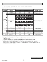
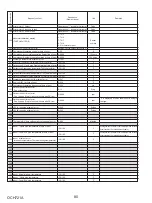
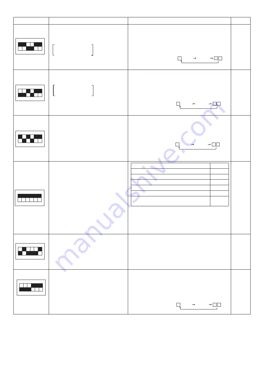
SW2 setting
Display detail
Explanation for display
Unit
°F
[°C]
0–327 (0–182°C)
(When the temperature is 100˚F or more,
hundreds digit, tens digit and ones digit are
displayed by turns.)
(Example) When 150°F;
0.5 s 0.5 s 2 s
50
1
Sub cool on error occurring. SC
0–234
Cooling = TH6−TH3
Heating = TH5−TH2
0–234 (0–130°C)
(When the temperature is 100˚F or more,
hundreds digit, tens digit and ones digit are
displayed by turns.)
(Example) When 115°F;
0.5 s 0.5 s 2 s
15
1
Thermo-ON time until error stops
0–999
0–999
(When it is 100 minutes or more, hundreds digit, tens
digit and ones digit are displayed by turns.)
(Example) When 415 minutes;
0.5 s 0.5 s 2 s
15
4
1
ON
2 3 4 5 6
Discharge superheat on error occurring
SHd
0–327
Cooling = TH4−TH6
Heating = TH4−TH5
1
ON
2 3 4 5 6
1
ON
2 3 4 5 6
°F
[°C]
Minute
1
ON
2 3 4 5 6
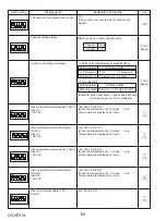
U9 Error details (To be shown while
error call is deferred.)
Pulse
LEV-B opening pulse
0–480
0–480
(When it is 100 pulse or more, hundreds digit, tens
digit and ones digit are displayed by turns.)
1
ON
2 3 4 5 6
Comp. surface temperature (TH33)
−4–422
1
ON
2 3 4 5 6
°F
[°C]
−4–422 (−20–217°C)
(When the comp. surface thermistor detects 100˚F
or more, hundreds digit, tens digit and ones digit are
displayed by turns.)
(Example) When 105°C;
0.5 s 0.5 s 2 s
05
1
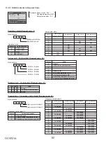
Error details
Code
Normal
00
Overvoltage error
01
Undervoltage error
02
Input current sensor error
04
Abnormal power synchronous signal
08
PFC error
(Overvoltage/Undervoltage/Overcurrent)
10
Display examples for multiple errors:
Overvoltage (01) + Undervoltage (02) = 03
Undervoltage (02) + Power-sync signal error (08) = 0A
L
1
-phase open error (04) + PFC error (10) = 14


