background image

27

Specifications are subject to change without notice. 


                                                                        © 2017 Mitsubishi Electric US, Inc.

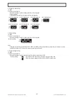
(3) Wiring

• 

A basic connection method is shown below.

CN24

X

X

Remote control board

Relay circuit

Adapter

Indoor unit

control board

ret

ae

H  

cirt

cel

E

ecr

uo

s r

e

wo

p

Red

1

White 2

Preparations in the field

Maximum cable length

is 10 m (32ft)

White

Electric Heater

or panel

heater

Outdoor unit

control board

• PUHY, PURY-P-TGMU

  type Dip switch SW5-2 

  “ON/OFF”
• PUHY, PURY-P-THMU/

  YHMU/TJMU/YJMU type

  Dip switch SW5-10 “ON/

  OFF”
• PUHY, PURY-P-TKMU/

  YKMU type Dip switch 

  SW4: 932 “ON/OFF”

• PUMY series

  Dip switch SW4-4 

  “ON/OFF”

• PUHY, PURY-P-TLMU/

  YKMU type Dip switch 

  SW4: 932 “ON/OFF”

CN22

White 

1

White 2

White

• 

The length of the electrical wiring for the CN24RELAY-KIT-CM3 is 2 meters (6-1/2 ft.)

• 

To extend this length, use sheathed 2-core cable.


Control cable type: CVV, CVS, CPEV or equivalent.


Cable size: 0.5 mm2 ~ 1.25 mm2 (16 to 22 AWG)


Don't extend the cable more than 10 meters (32ft)

Recommended circuit

Wiring diagram

1-phase power

supply
208V, 230V/60Hz

Control board

FS1, 2 ----- Thermal fuse
H1, H2 ----- Heater
26H --------- Overheat protection

thermostat

88H --------- Electromagnetic contactor

FS1

FS2

FS1

FS2

R
S

R
S

CN24-1 or CN24-2

H2

88H

H1

88H

26H

88H

(4) Wiring restrictions

• 

Keep the length of the cable connecting to the circuit board of the indoor unit shorter than 10 meters (32ft).

• 

Longer than 10 meters (32ft) could cause improper operation.

• 

Use a transit relay when extending wiring such as remote wiring.

Summary of Contents for PVFY-P12 NAMU-E

Page 1: ... Series PVA 2015 PVA A30AA4 PVA A36AA4 PVA A42AA4 INDOOR UNIT Air Conditioners PVFY P12 18 24 30 36 48 54NAMU E1 Multi Position Air Handler SPLIT TYPE HEAT PUMP AIR CONDITIONERS SERVICE MANUAL Model name Indoor unit Model name Indoor unit Series PVA 2015 PVA A30AA4 PVA A36AA4 PVA A42AA4 INDOOR UNIT ...

Page 2: ......

Page 3: ...CAUTION 2 2 FEATURES 5 3 PART NAMES AND FUNCTIONS 6 4 SPECIFICATION 9 5 OUTLINES DIMENSIONS 13 6 WIRING DIAGRAM 15 7 REFRIGERANT SYSTEM DIAGRAM 16 8 MICROPROCESSOR CONTROL 17 9 TROUBLESHOOTING 29 10 DISASSEMBLY PROCEDURE 39 ...

Page 4: ...ring use during repair or at the time of disposal of the unit It may also be in violation of applicable laws MITSUBISHI ELECTRIC CORPORATION cannot be held responsible for malfunctions or accidents resulting from the use of the wrong type of refrigerant Ask your dealer or a qualified technician to install the unit Improper installation by the user may result in water leak age electric shock or fir...

Page 5: ...frigerant cycle and may cause the pipes to burst or explode When installing the unit in a small space take appropriate precautions to prevent leaked refrigerant from reaching the limiting concentration Leaked refrigerant gas will displace oxygen and may cause oxygen starvation Consult your dealer before installing the unit Consult your dealer or a qualified technician when moving or reinstalling t...

Page 6: ... phase If gaseous refrigerant is drawn out of the cylinder first the composition of the remaining refrigerant in the cylinder will change and become unsuitable for use Only use R410A The use of other types of refrigerant that contain chloride may cause the refrigerator oil to deteriorate Use a vacuum pump with a check valve If a vacuum pump that is not equipped with a check valve is used the vacuu...

Page 7: ...l Cooling capacity Heating capacity Btu h kW PVFY P12NAMU E1 12000 13500 3 5 4 0 PVFY P18NAMU E1 18000 20000 5 3 5 9 PVFY P24NAMU E1 24000 27000 7 0 7 9 PVFY P30NAMU E1 30000 34000 8 8 10 0 PVFY P36NAMU E1 36000 40000 10 6 11 7 PVFY P48NAMU E1 48000 54000 14 1 15 8 PVFY P54NAMU E1 54000 60000 15 8 17 6 ...

Page 8: ...ject to change without notice 2017 Mitsubishi Electric US Inc PART NAMES AND FUNCTIONS 3 1 Indoor Unit Air inlet Air outlet 1 Vertical 2 Horizontal Right Air inlet Air outlet Air inlet Air outlet 3 Horizontal left 4 Down flow ...

Page 9: ...lamp will light up in green when turned on and blink during startup and when an error occurs Pressing this button starts and stops the operation Keep the remote controller out of direct sunlight to ensure accurate measurement of room temperature The thermistor at the lower right hand section of the remote controller must be free from obstructions to ensure accurate measurement of room temperature ...

Page 10: ...or code blinks icon appears while the unit is operated in the energy save mode All icons are displayed for explanation icon appears when Operation lock setting is effective icon appears when indoor unit functions are set up Refer to the Installation Manual Fan speed icon Vane icon icon appears when the power is on Indoor temperature Operation modes CENTRAL icon 1 CHECK icon 2 Preset temperature 3 ...

Page 11: ...00 410 497 585 515 625 735 m min 7 9 9 6 11 3 11 6 14 1 16 6 14 6 17 7 20 8 L s 132 160 188 193 235 277 243 295 347 Sound pressure level Low Mid High measured in anechoic room dB A 27 31 35 28 32 36 30 34 38 Insulation material EPS Polyethylene foam Urethane foam Polyester Air filter PP honeycomb fabric Protection device Fuse Refrigerant control device LEV Connectable outdoor unit R410A CITY MULTI...

Page 12: ...Mid High CFM 613 744 875 767 931 1095 m min 17 3 21 1 24 8 21 7 26 4 31 0 L s 290 352 413 362 440 517 Sound pressure level Low Mid High measured in anechoic room dB A 32 36 40 35 39 43 Insulation material EPS Polyethylene foam Urethane foam Polyester Air filter PP honeycomb fabric Protection device Fuse Refrigerant control device LEV Connectable outdoor unit R410A CITY MULTI Diameter of refrigeran...

Page 13: ...id High CFM 980 1190 1400 1040 1262 1485 m min 27 7 33 7 39 6 29 4 35 7 42 0 L s 463 562 660 492 595 702 Sound pressure level Low Mid High measured in anechoic room dB A 35 39 43 36 40 44 Insulation material EPS Polyethylene foam Urethane foam Polyester Air filter PP honeycomb fabric Protection device Fuse Refrigerant control device LEV Connectable outdoor unit R410A CITY MULTI Diameter of refrige...

Page 14: ...supply terminal block TB2 L1 L2 G 250V 20A Transmission terminal block TB5 TB15 1 2 250V 15A M1 M2 S 250V 20A Component Symbol PVFY P30NAMU E1 PVFY P36NAMU E1 Room temperature thermistor TH21 Resistance 0 C 15kΩ 10 C 9 6kΩ 20 C 6 3kΩ 25 C 5 4kΩ 30 C 4 3kΩ 40 C 3 0kΩ Liquid pipe thermistor TH22 Resistance 0 C 15kΩ 10 C 9 6kΩ 20 C 6 3kΩ 25 C 5 4kΩ 30 C 4 3kΩ 40 C 3 0kΩ Gas pipe thermistor TH23 Resis...

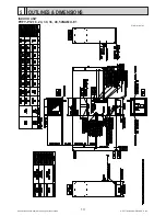
Page 15: ...Specifications are subject to change without notice 2017 Mitsubishi Electric US Inc 13 OUTLINES DIMENSIONS 5 INDOOR UNIT PVFY P12 18 24 30 36 48 54NAMU E1 Unit mm in ...

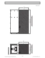
Page 16: ...ecifications are subject to change without notice 2017 Mitsubishi Electric US Inc 14 609 6 24 Width of Unit 609 6 24 Length of Unit Clearance Area Vertical Installation Horizontal Installation Unit mm in ...

Page 17: ...idity input Connector Remote indication LED Power supply LED Remote controller supply Switch connection No set Switch for static pressure selection Switch for static pressure selection Connector emergency operation Switch for mode selection Switch for capacity code Switch for mode selection Switch for model selection Switch for mode selection Switch 1st digit address set Switch 10ths digit address...

Page 18: ...AMU E1 H I F E E C G A D B A Gas pipe thermistor TH23 B Gas pipe C Liquid pipe D Brazed connections E Strainer 100 mesh F Linear expansion valve G Liquid pipe thermistor TH22 H Heat exchanger I Room temperature thermistor TH21 Capacity PVFY P12 18NAMU E1 PVFY P24 30 36 48 54NAMU E1 Gas pipe ø12 7 1 2 ø15 88 5 8 Liquid pipe ø6 35 1 4 ø9 52 3 8 ...

Page 19: ...i freezing control starts and the thermo OFF Released condition The timer which prevents reactivating is set for 3 minutes and anti freezing control is cancelled when any one of the following conditions is satisfied 1 Liquid pipe temp TH22 turns 50 F or above 2 The condition of the thermo OFF has become complete by thermo regulating etc 3 The operation modes became mode other than COOL 4 The opera...

Page 20: ...thermo ON time min Dry thermo OFF time min Thermo regulating signal Room temperature T1 Over 64 F ON T1 83 F 9 3 83 F T1 79 F 7 3 79 F T1 75 F 5 3 75 F T1 3 3 OFF Unconditional 3 10 Less than 64 F Dry thermo OFF 2 Frozen prevention control No control function 2 Fan 1 Indoor fan operation controlled depends on the compressor conditions Dry thermo Fan speed notch ON Low OFF Room temp 64 F Stop Room ...

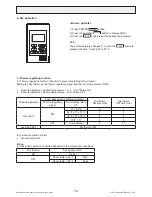
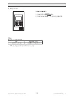
Page 21: ...itsubishi Electric US Inc 3 Fan operation 1 Fan 1 Set by remote controller Type Fan speed notch 3 speeds Auto type Low Med High Auto When Auto is set fan speed becomes Low How to operate 1 Press POWER ON OFF button 2 Press the operation MODE button to display FAN ...

Page 22: ...Hot adjust mode 2 Preheating exclusion mode 3 Thermo OFF mode When the compressor off by the thermo regulating 4 Cool air prevention mode Defrosting mode 5 Capacity increasing mode 2 Hot adjust mode The fan controller becomes the hot adjuster mode for the following conditions 1 6 When starting the HEAT operation 1 7 When the thermo regulating function changes from OFF to ON 1 8 When release the HE...

Page 23: ... fan operates in Low mode for 1 minute Note This control is same for the model without auxiliary heater 4 Thermo OFF mode When the thermo regulating function changes to OFF the indoor fan operates in Extra low 5 Heat defrosting mode The indoor fan stops 1 Initial value of operation mode 1 HEAT mode for room temperature Desired temperature 2 COOL mode for room temperature Desired temperature 2 Mode...

Page 24: ... 932 OFF PUMY S W4 4 OFF N A OFF Heater not Available ON OFF Heater Available OFF OFF ON ON Heater Available ON ON 2 DIP S W ON In the case of TGMU S W5 2 ON THMU YHMU TJMU YJMU S W5 10 ON TKMU YKMU SW4 932 ON TLMU YLMU SW4 932 ON PUMY S W4 4 ON Normal drive Defrost drive H P drive H P stop Condition of O U 㻼㼍㼞㼍㼙㼑㼠㼑㼞㼟㻌a b c d are set by㻌 maintenance tool a b c d Outdoor temp Normal drive OFF Heate...

Page 25: ...er 2 To Set point temperature TRA Return Air temperature X Time delay Selectable Default is 20 min Selectable to 10 15 or 25 min Table 3 shows how the time delay is selected Table 3 Time Delay Selection Table Function Setting 1 Action 3 108 1 Set Time Delay to 10 minutes 108 2 Set Time Delay to 15 minutes 108 3 Set Time Delay to 20 minutes 2 108 4 Set Time Delay to 25 minutes 1 Time delay can only...

Page 26: ...Example Step Condition Result To TRA 2 7 F 1 5 C AND TRA has not increased by 0 9 F 0 5 C in X min EH1 ON To TRA 2 7 F 1 5 C AND TRA increasing faster than 0 9 F 0 5 C in 5 min EH2 not ON To TRA 0 9 F 0 5 C EH1 OFF To TRA 2 7 F 1 5 C AND TRA has not increased by 0 9 F 0 5 C in X min EH1 ON To TRA 2 7 F 1 5 C AND TRA not increasing faster than 0 9 F 0 5 C in 5 min EH2 ON To T RA 0 9 F 0 5 C EH1 OFF...

Page 27: ...F Stop Heater OFF Stop Heater ON 4 ON Low Heater OFF Low Heater ON Stop Heater OFF Stop Heater ON 1 Heater will not operate during all error modes Heater will only operate during a communication error between indoor unit and outdoor unit 2 While the heater is on the fan will operate at high speed regardless of the fan setting on the remote controller If a heater is installed in the duct do not use...

Page 28: ...escribes installation of the External Heater Adapter that connects to PEA A AA series indoor unit This products is the special wiring parts to drive an electric heater wi th the air conditioner 1 Parts list Check that the following par ts are included in the package 1 External output cable with a yellow connector 2 in total Tw o types of cables with differen t connectors are included 2 Panel heate...

Page 29: ...U type Dip switch SW4 932 ON OFF CN22 White 1 White 2 White The length of the electrical wiring for the CN24RELAY KIT CM3 is 2 meters 6 1 2 ft To extend this length use sheathed 2 core cable Control cable type CVV CVS CPEV or equivalent Cable size 0 5 mm2 1 25 mm2 16 to 22 AWG Don t extend the cable more than 10 meters 32ft Recommended circuit Wiring diagram 1 phase power supply 208V 230V 60Hz Con...

Page 30: ...mote controller The fan continues to run for 30 seconds after the humidifier stops CNF CN25 Humidistat XA SVA Humidifier XA Indoor unit control board On site preparation Maximum cable length is 10m 32ft Humidifier power source Use XA relay having following specifications Rated voltage 12VDC Power consumption 1W or less Humidistat Minimum applicable load 1mA at DC Contact rating voltage 15VDC or mo...

Page 31: ...perature thermistor TH21 Liquid pipe thermistor TH22 Gas pipe thermistor TH23 Drain sensor DS Thermistor R0 15 kΩ 3 Multiplier of B 3480 kΩ 2 0 C 32 F 15kΩ 10 C 50 F 9 6kΩ 20 C 68 F 6 3kΩ 25 C 77 F 5 2kΩ 30 C 86 F 4 3kΩ 40 C 104 F 3 0kΩ A Temperature C F B Resistance kΩ 0 10 20 30 40 50 20 10 0 10 20 30 40 50 4 14 32 50 68 86 104 122 A B 2 Fan motor CNMF Refer to the page on DC fan motor fan motor...

Page 32: ...C D D E E F F 12VDC M 4 6 2 3 5 1 A Red G Control board C Blue H Connection CN60 D Orange I Drive circuit E Yellow J Linear expansion valve F White Pulse signal output and valve operation Phase number Output pulse 1 2 3 4 ø1 ON OFF OFF ON ø2 ON ON OFF OFF ø3 OFF ON ON OFF ø4 OFF OFF ON ON The output pulse changes in the following order When the valve closes 1 2 3 4 1 When the valve opens 4 3 2 1 4...

Page 33: ...r 3 Troubleshooting Symptom Checking Criteria Remedy Circuit failure on the microcomputer Disconnect the connectors on the control board and connect LEDs to test the circuit as shown below Replace the indoor control board if driving circuit failure is detected 6 5 4 3 2 1 1 k LED Pulse signals are output for 10 seconds when the main power is turned on If there are LEDs that do not light up at all ...

Page 34: ...f the amount of leakage is great A LEV A Termistor TH22 Normally the LEV is fully closed while the unit is in the FAN mode If the valve is leaky liquid pipe thermistor reading will be lower than normal If it is significantly lower than the inlet temperature on the remote controller valve closure failure is suspected If the amount of leakage is insignificant replacement of LEV is unnecessary unless...

Page 35: ...sistance PVFY P12 18 24 30 36 NAMU E1 PVFY P48 54 NAMU E1 pin 1 pin 4 pin 5 pin 4 50kΩ pin 6 pin 4 150kΩ O L O L 47kΩ 143kΩ 1MΩ O L pin 7 pin 4 Replace indoor controller board I B Replace fan motor MF Replace indoor controller board Is the resistance of the fan motor normal Refer to below table Does the voltage between pin 7 and pin 4 of connector CNMF repeat 0V and 5V Replace the fan motor Is the...

Page 36: ...OFF A B A Indoor unit control board B Factory setting all models 1 Address settings vary in different systems Refer to the section on address setting in the outdoor unit installation manual 2 Address is set with a combination of SW12 10 s digit and SW11 1 s digit To set the address to 3 set SW12 to 0 and SW11 to 3 To set the address to 25 set SW 12 to 2 and SW 11 to 5 ...

Page 37: ... cable connection 10 13 VDC Between 1 and 3 CN52 Remote display CN51 Centralized control CN41 JAMA standard HA terminal A CN44 Thermistor liquid gas temperature CN4F Float sensor CN22 For fan control CN24 1 For 1st heater control CN24 2 For 2nd heater control CN20 Thermistor Inlet temperature CNMF Fan motor output 1 4 294 340 VDC 5 4 15 VDC 6 4 0 6 5 VDC 7 4 Stop 0 or 15 VDC Run 7 5 VDC 0 15 pulse...

Page 38: ...difier operation During heating mode During heating operation 7 Fan speed Low Very low 8 Fan speed at heating Thermo OFF Preset fan speed Follows the setting of SW1 7 9 Auto restart after power failure Enabled Disabled 10 Power start stop Enabled Disabled 1 Adress board Factory setting 2 SW3 Switch position Function Switch setting ON OFF 1 Unit type Cooling only Heat pump 2 Heater available Heater...

Page 39: ...VFY P54NAMU E1 3 Model setting 1 SW4 1 Indoor control board Dipswitch settings must be made while the unit is stopped Factory setting Note Changes made to the dipswitches SW1 SW2 and SW3 will become effective when the unit comes to a stop remote controller off There is no need to power cycle the unit 4 Power voltage setting 1 SW5 1 Indoor control board Dipswitch settings must be operated with the ...

Page 40: ... 2 1 2 1 2 2 1 2 1 2 Factory setting 1 2 3 SWA SWC 1 2 Note Changes that are made to the dipswitches SWA and SWC immediately become effective regardless of the unit s operation status RUN STOP or the remote controller status ON OFF 6 1s and 10ths digits 1 SW11 SW12 Rotary switch The use of a ME remote controller requires address setting 1 Indoor control board Address settings must be made while th...

Page 41: ...ecifications are subject to change without notice 2017 Mitsubishi Electric US Inc 1 Control box Exercise caution when removing heavy parts 1 Remove the Electric panel 2 screws Fig 1 10 DISASSEMBLY PROCEDURE ...

Page 42: ...TING FINE COARSE PRESS WORKING GAS CUTTING A B SHEARING A B MACHINING MEDIUM COARSE E D C B A MITSUBISHI ELECTRIC CORPORATION DATE APPROVED DRAWN CHECKED DESIGNED 3D CONFIDENTIAL ITEM MODEL NAME 1 15 Creo 0_TOP_ASSY_L_21554B2 drw Fig 3 2 Remove the Blower panel 2 screws 3 Remove the cover over the Return Air thermistor box and unplug the thermistor 4 Pull out the thermistor holder and thermistor i...

Page 43: ... C D E F G H I J 15 14 13 12 11 10 9 8 7 6 5 4 3 2 1 SCALE NTS MITSUBISHI ELECTRIC CORPORATION DATE APPROVED DRAWN CHECKED DESIGNED 3D 1 5 Creo 0_TOP_ASSY_L_21554B2 drw DETAIL A DETAIL B OUTSIDE COIL SCREWS Fig 5 3 Slide the smaller panels in the directions indicated and remove Fig 6 4 Remove the 1 or 2 brackets that secure the coil unplug the thermistors and LEV from the control board and route t...

Page 44: ... Specifications are subject to change without notice 2017 Mitsubishi Electric US Inc 5 Remove the plate covering the coil assembly to access the thermistors Fig 9 6 Remove lower and side drain pan Fig 10 ...

Page 45: ...wer and Filter panel along with filter if installed indicated in section 2 2 Remove the 1 or 2 brackets that secure the coil assembly Fig 11 Fig 11 3 Remove the door that covers the small enclosure attached to the fan assembly Fig 12 Unplug the motor and route the wire harness out of the enclosure 4 Remove the 2 screws that secure the fan assembly and slide out Fig 12 ...

Page 46: ...tric US Inc www mitsubishielectric usa com Toll Free 800 433 4822 MITSUBISHI ELECTRIC US INC Please be sure to put the contact address telephone number on this manual before handing it to the customer This product is designed and intended for use in the residential commercial and light industrial environment ...

Reviews: