background image

HEAD OFFICE

: TOKYO BLDG., 2-7-3, MARUNOUCHI, CHIYODA-KU, TOKYO 100-8310, JAPAN

10.  Service menu <Administrator password is required.>

Select “Service menu” from the Main menu > Commissioning and press the 

 button.

The service menu will appear.

Note: 
 The following settings can be made from the Maintenance Information screen.

•  Registering model names and serial numbers

Enter the model names and serial numbers of Lossnay unit. The information entered will 
appear on the Error information screen. Model names can have up to 18 characters, and the 
serial numbers can have up to 8 characters.

•  Registering dealer information

Enter phone number of a dealer. The entered information will appear on the Error information 
screen. Phone number can have up to 13 characters.

•  Initializing maintenance information

Select the desired item to initialize the above settings.

(2) Function setting

Make the Lossnay units' function settings from the remote controller as necessary. 
•  Refer to the Lossnay unit Installation Manual for information about the factory settings of Lossnay units, function setting numbers, and 

setting values. 

•  When changing the Lossnay units' function settings, record all the changes made to keep track of the settings.
•  Refer to the Instruction Book for the remote controller.

(3) Initializing the settings of the remote controller

Refer to the Instruction Book for the remote controller.

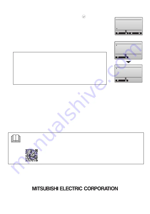
Commissioning menu     1/2

Initial setting
Airflow
Auto bypass
External input
Service

Cursor

Page

Main menu:

(1) Input maintenance Info.

Select “Input maintenance Info.” from the Service menu to bring up the Maintenance information 
screen. Refer to the Lossnay unit Installation Manual for how to make the settings.
The service menu will appear.

Maintenance information

Model name input
Serial No. input
Dealer information input
Initialize maintenance info.

Cursor

Main menu:

Service menu

Cursor

Input maintenance info.
Function setting
Initializing

Main menu:

May 2021

Manual Download

Go to the website below to download manuals, select model name, then choose language.

http://www.mitsubishielectric.com/ldg/ibim/

Eng-14

Summary of Contents for PZ-62DR-E

Page 1: ...er electrical parts with wet hands To reduce the risk of injury or electric shock before spraying a chemical around the controller stop the operation and cover the controller To reduce the risk of injury or electric shock stop the operation and switch off the power supply before cleaning maintaining or inspecting the controller Properly install all required covers to keep moisture and dust out of ...

Page 2: ... To reduce the risk of electric shock shorting or malfunctions keep wire pieces and sheath shavings out of the terminal block To reduce the risk of shorting current leakage electric shock or malfunctions keep the cables out of contact with controller edges To reduce the risk of electric shock malfunctions or fire seal the gap between the cables and cable access holes with putty The controller shou...

Page 3: ...ol panel door Vibrations or shocks to the controller may damage the controller or cause the controller to fall Hold the cables in place with clamps to prevent undue force from being applied to the terminal block and causing cable breakage To prevent cable breakage and malfunctions do not hang the top controller casing hang by the cable Parts name Qty Appearance Remote controller front cover 1 Righ...

Page 4: ...ntroller cable Use a 0 3 mm AWG22 2 core sheathed cable Necessary 2 Installation space Leave a space around the remote controller as shown in the figure at right regardless of whether the controller is installed in the switch box or directly on the wall Removing the remote controller will not be easy with insufficient space Also leave an operating space in front of the remote controller Important ...

Page 5: ...ler cable access hole at the connection of switch box and conduit tube with putty 3 Prepare the bottom case of the remote controller Direct wall installation Seal the hole through which the cable is threaded with putty To reduce the risk of electric shock malfunctions or fire seal the gap between the cables and cable access holes with putty Wall Conduit tube Locknut Switch box Seal the gap with pu...

Page 6: ...the cover indicated with the shaded area in the right figure with a knife or a nipper Thread the cable from the groove behind the bottom case through this access hole Installation using a switch box Direct wall installation Seal the cable access hole with putty Double switch box Roundhead cross slot screws Remote controller cable Wood screw Remote controller cable Thread the cable through the groo...

Page 7: ...he terminal block and causing cable breakage Important Clamp Insert the wire When attaching the cover and the top casing to the bottom casing push it until it they click into place If they are not properly locked into place they may fall causing personal injury controller damage or malfunctions Important Direct wall installation when running the cable along the wall Thread the cable through the ac...

Page 8: ...ase Two mounting tabs are at the top of the top case Hook those two tabs onto the bottom case and click the top case into place Install the cover on the top case in the same way as with the top case Check that the top case is securely installed and not lifted When attaching the cover and the top casing to the bottom casing push it until it they click into place If they are not properly locked into...

Page 9: ...ations on the Main menu Note When the backlight is off pressing any button turns the backlight on and does not perform its function except for the button Note If the function is not set in the function button the function button guide will not be displayed Pressing the button will bring up the Main menu as shown below Refer to section 8 2 Main display for details User options 1 3 Commissioning 1 2...

Page 10: ... Administrator password Main display While the unit is in operation Note Only the first time the Language selection screen will be appeared The product will not start up without language selection See 9 6 Language selection Lossnay Outdoor 2 C Return 2 C Fan Mode Auto Lossnay 12 Sun 12 Sun Main Main display Cursor Main menu User options Commissioning Maintenance Commissioning menu 1 2 Initial sett...

Page 11: ...save the change The change will be reflected on the clock display on the Main display 3 Display contrast Button operation Adjust LCD contrast with the or button The current level is indicated with a triangle Press the button to move the cursor Press the button to go to the next screen Initial setting menu 1 2 Main Sub Clock Contrast Display details Administrator password Cursor Page Main menu Init...

Page 12: ...s screen and select the desired setting with the or button The factory setting is No Yes Outdoor return and supply temperatures appear on the Main display No Outdoor return and supply temperatures do not appear on the Main display 4 Remote controller display details setting Make the settings for the remote controller related items as necessary Press the button to save the changes Clock display Cur...

Page 13: ...enska Français Español Português Русский Language selection 1 2 Cursor Cursor Select Nederlands Language selection 2 2 Cursor Administrator password Enter administrator password Change administrator password Select Cursor Administrator password Enter administrator password Update administrator password Cancel OK Note The administrator password is required to make the settings for Commissioning men...

Page 14: ...essary Refer to the Lossnay unit Installation Manual for information about the factory settings of Lossnay units function setting numbers and setting values When changing the Lossnay units function settings record all the changes made to keep track of the settings Refer to the Instruction Book for the remote controller 3 Initializing the settings of the remote controller Refer to the Instruction B...

Reviews: