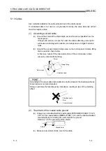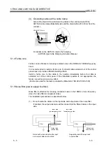
6 - 3 6 - 3
MELSEC
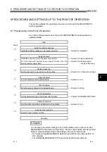
6 PROCEDURE AND SETTINGS UP TO THE POINT OF OPERATION
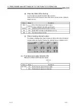
No. Name
Description
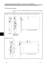
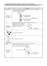
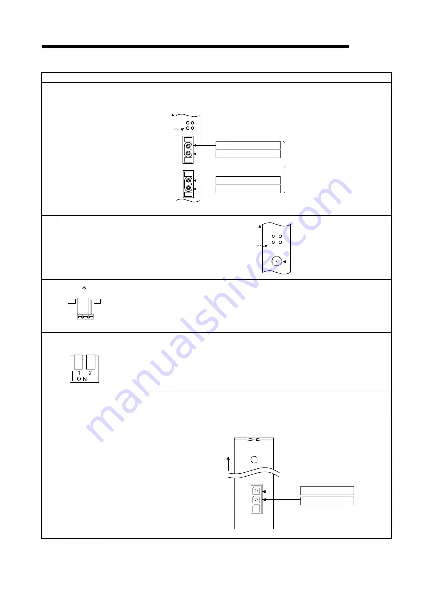
1) Indicator
LED
Indicates the operating status of the MELSECNET/H board. Refer to (1) in this Section.
2)
Connector for
connecting
optical fiber cable
Connector for connecting optical fiber cable.
The cable terminal is as shown below.
Optical fiber cable
connection connector
LED
IN
OUT
RUN
L
ERR.
SD
RD
IN
Forward loop reception
IN
Reverse loop transmission
Reverse loop reception
OUT
Forward loop transmission
OUT
Refer to Section 6.4, "Cable Connections." for wiring of the optical fiber cable.
3)
Connector for
connecting
coaxial cable
Connector for connecting coaxial cable.
The cable terminal is as shown below.
Refer to Section 6.4, "Cable Connections."
for wiring of the coaxial cable.
4)
Jumper
1
RP
LB
Use prohibited (Fixed to RP side)
5)
DIP switch
Use prohibited (Fixed to OFF)
6)
External power
supply indicator
LED
Indicates the status of external power supply. Refer to (2) in this Section.
7)
External power
supply cable
connector
Connector for connecting external power supply cable
The cable terminal assignment is as shown below.
EXT.PW
CLASS2 ONLY
24V
24G
EXT.PW
(With the board top facing up)
LED
Coaxial cable
connection connector
RUN
L
ERR.
SD RD
Summary of Contents for Q80BD-J71BR11
Page 2: ......
Page 24: ...A 22 A 22 MEMO ...
Page 50: ...4 6 4 6 MELSEC 4 FUNCTION MEMO ...
Page 92: ...6 36 6 36 MELSEC 6 PROCEDURE AND SETTINGS UP TO THE POINT OF OPERATION MEMO ...
Page 132: ...10 2 10 2 MELSEC 10 MELSEC DATA LINK LIBRARY MEMO 10 ...
Page 138: ...11 6 11 6 MELSEC 11 PROGRAMMING MEMO ...
Page 164: ...12 26 12 26 MELSEC 12 APPLICATION FUNCTIONS MEMO ...
Page 166: ...13 2 13 2 MELSEC 13 ERROR CODE MEMO 13 ...
Page 223: ......

