6 - 8 6 - 8
MELSEC
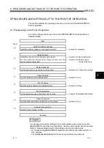
6 PROCEDURE AND SETTINGS UP TO THE POINT OF OPERATION
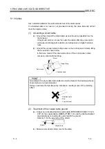
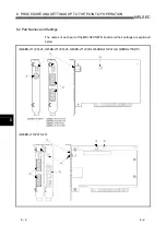
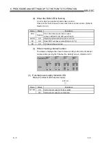
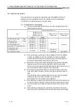
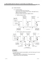
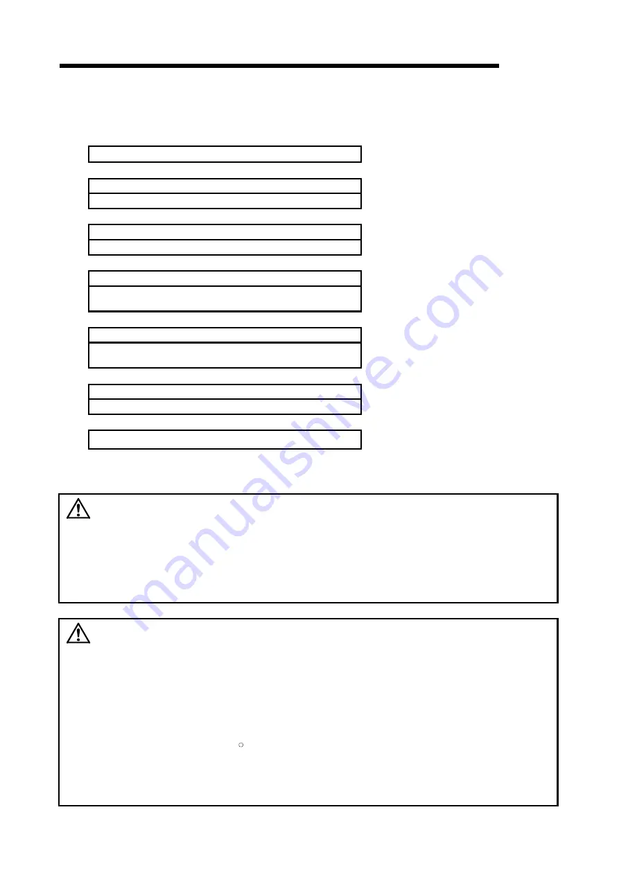
6.3.3 Board installation
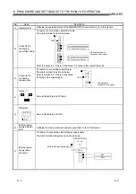
The following flowchart shows the board installation procedure.
Start
↓
Power OFF
Power OFF the personal computer.
↓
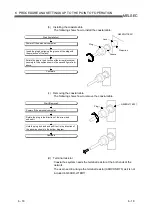
Install the board
Install the board to a slot on the personal computer.
↓
Fix the board
Fix the board to a slot on the personal computer using the board-
fixing screws.
↓
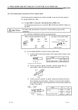
Wiring the external power supply cable
For the board with external power supply function, wire the
external power supply cable.
Refer to Section 6.4.4
↓
Power ON
Power ON the personal computer.
↓
End
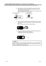
For the installation method of the board to a slot, refer to the instruction manual
provided with the personal computer.
WARNING
•
Be sure to shut off all phases of the external power supply used by the system
before performing work such as installing the board and wiring.
If all power is not turned off, there is a risk of electric shock or damage to the
product.
•
When turning on the power and operating the module after having installed the
board and doing the wiring, always attach the cover for the device module in
which the board is installed.
There is a risk of electric shock if the module cover is not attached.
CAUTION
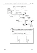
•
Fix the board by tighten the board-fixing screws within the specified torque range.
Under tightening may cause malfunction, short circuit, or malfunction. Over
tightening may damage the screw and/or module, resulting in drop, short circuit,
or malfunction. For the tightening torque of the board fixing screws, refer to the
manual supplied with the personal computer.
•
Always make sure to touch the grounded metal to discharge the electricity
charged in the body, etc., before touching the board.
Failure to do so may cause a failure or malfunctions of the board.
•
Install the board to a personal computer which is compliant with PCI standard or
PCI Express
R
standard (Refer to "Section 2.5 Operating Environment").
Failure to do so may cause a failure or malfunction.
•
Securely mount the board to the PCI slot of the mounting device.
If the board is not mounted correctly, this may lead to malfunctioning, failure or
cause the board to fall.
Summary of Contents for Q80BD-J71BR11
Page 2: ......
Page 24: ...A 22 A 22 MEMO ...
Page 50: ...4 6 4 6 MELSEC 4 FUNCTION MEMO ...
Page 92: ...6 36 6 36 MELSEC 6 PROCEDURE AND SETTINGS UP TO THE POINT OF OPERATION MEMO ...
Page 132: ...10 2 10 2 MELSEC 10 MELSEC DATA LINK LIBRARY MEMO 10 ...
Page 138: ...11 6 11 6 MELSEC 11 PROGRAMMING MEMO ...
Page 164: ...12 26 12 26 MELSEC 12 APPLICATION FUNCTIONS MEMO ...
Page 166: ...13 2 13 2 MELSEC 13 ERROR CODE MEMO 13 ...
Page 223: ......


