8
CC IE Control UTILITY
8.5 Diagnostics Screen
8.5.1 CC-Link IE Controller Network diagnostics result screen
8
- 31
1
OVE
R
VI
EW
2
SYS
TEM
CONFIGURA
T
ION
3
SP
ECIFI
C
A
T
IO
N
S
4
FUNCT
IONS
5
E
M
C
AND LOW
V
O
LT
A
G
E DIRECTIVE
6
P
R
OCEDURES
AND
SETTI
NGS BEFO
RE
O
PERA
T
IO
N
7
IN
ST
A
LLI
NG
AN
D
UN
IN
S
TAL
LI
N
G
S
O
F
T
W
AR
E P
A
CK
AG
E
S
8
CC
IE
Co
nt
rol
UT
ILITY
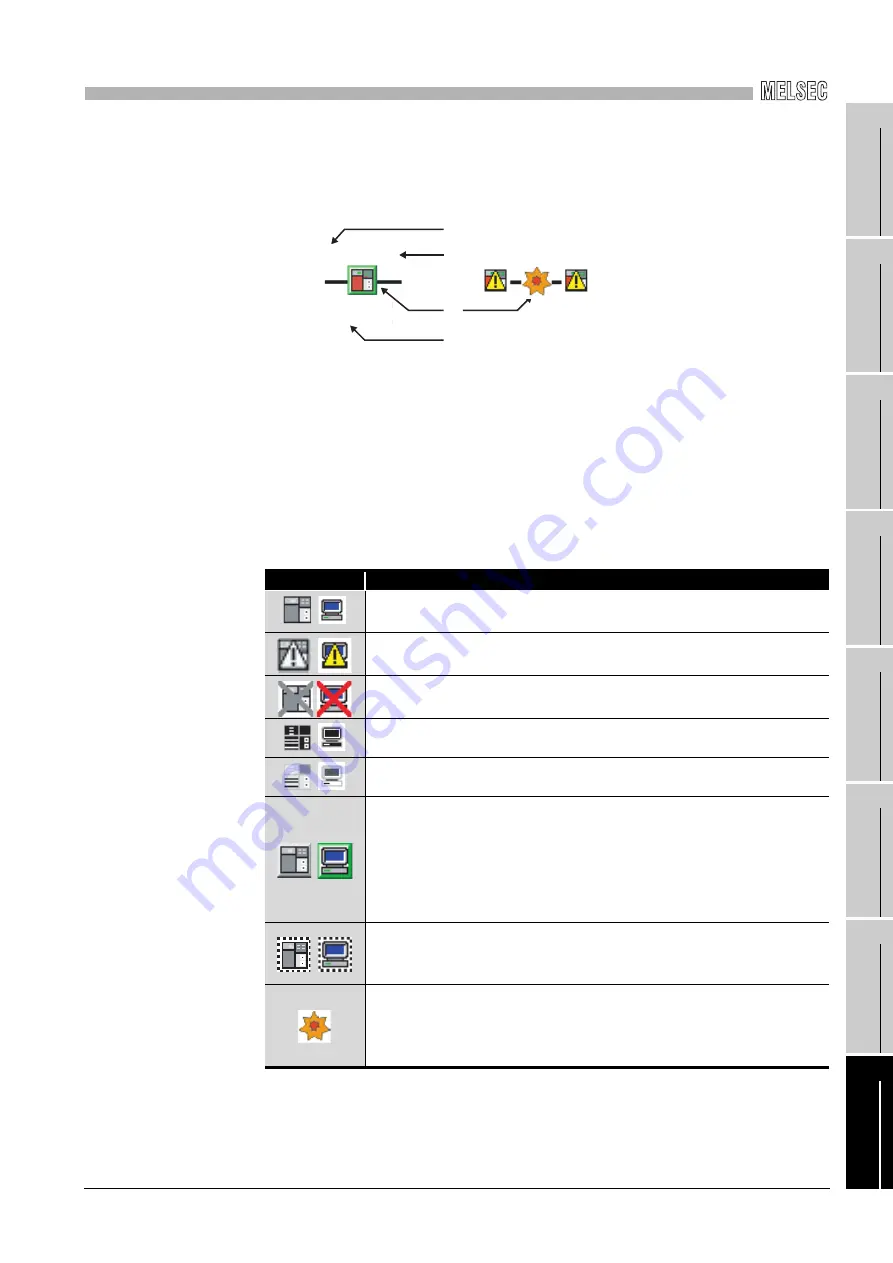
(2) Icon
Displays the status of each station and between stations.
1) Station number
Displays station number of the CC-Link IE Controller Network module or CC-
Link IE Controller Network board.
2) Connected station
"Connected" is displayed at the back of the station number for connected
stations.
3) Icon
The following table shows the description of station icons displayed.
4) Present Control and Assign Control
Present Control: Displayed to the station actually operating as a control station.
Assign Control: Displayed to the control station set in the parameter.
Icon
Description
Normally operating station
Faulty station (Although cyclic transmission is in operation, an error is
occurring in boards, modules or cables.)
Faulty station (Cyclic transmission is stopped.)
Disconnected station (black)
Reserved station (gray)
Selected station (green edged station icon)
• Can be selected by clicking a station icon, or moving the focus with the
right or left arrow key, and clicking the space bar.
• Displays detailed information in "Select station network device status
display" field.
• Disconnected stations and reserved stations cannot be selected.
Focusing (Station icon edged with dotted line)
• Clicking a space bar changes to a selected station.
• Disconnected stations and reserved stations cannot be selected.
Communication error
• Displays detailed information in "Select station network device status
display" field, when selecting the station next to the one in which a
communication error is occurring.
1)
2)
3)
4)
3
1 Connected
Present Control
Assign Control
4


