background image

APPENDICES

Appendix 1  Precautions for Accessing Redundant CPU System


App

 - 6

9

DEVICE MONIT

O

UT

IL

ITY


10

MELS

EC D

A

TA

 LI

N

K


LI

BRAR

Y

11

PROGRAMMING

12

AP

PLI

C

A

T

IO

N


FUNCT

IONS

13

E

R

ROR COD

E

S

14

TROU

BL

E

S

H

O

O

T

ING

A

A

P

PENDICES

I

INDEX

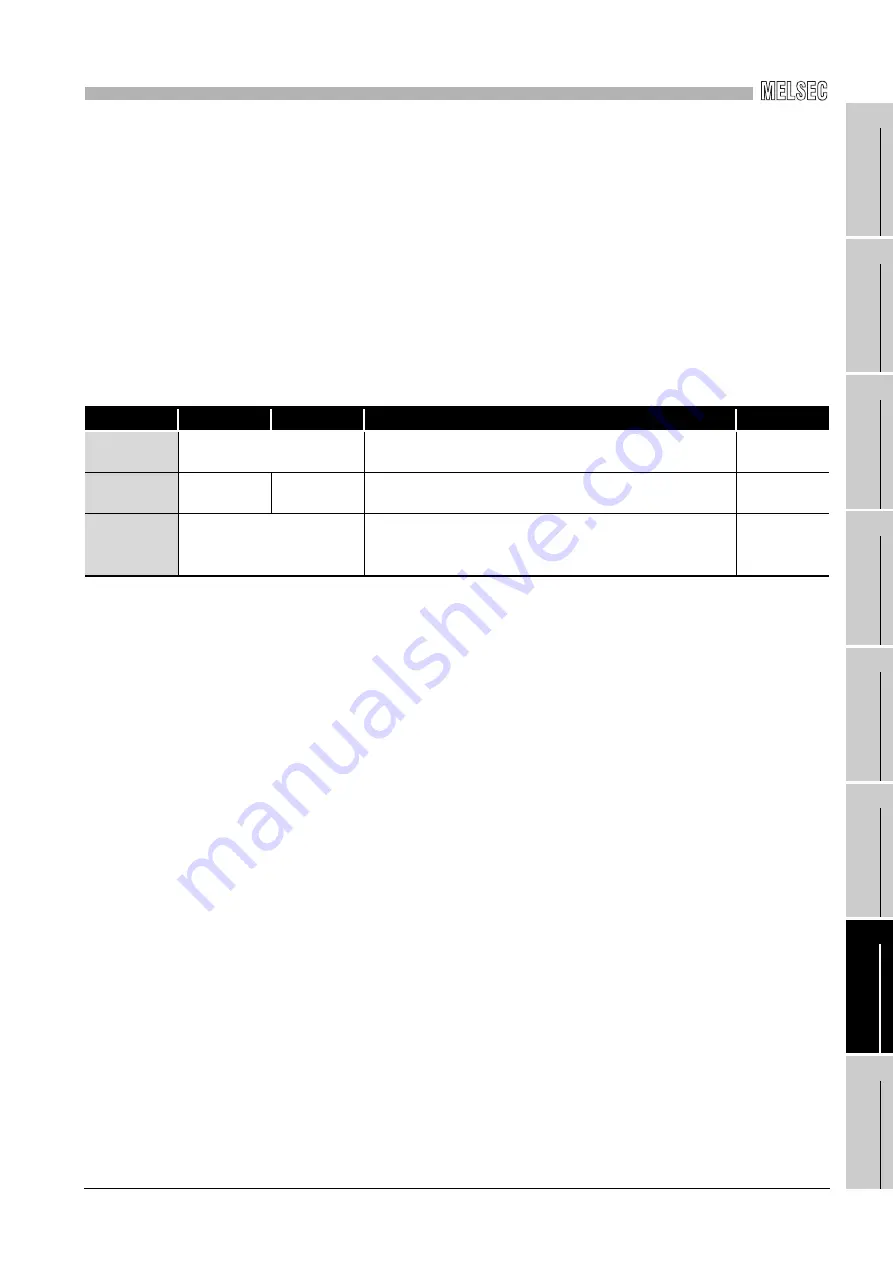
(b) Checking method of path switching occurrence and access examples of path 

switching

1) Checking method of path switching occurrence

When the system is communicating with the redundant system specified, 
whether communication is continued by path switching due to communication 
error occurrence can be estimated.
Create a program that monitors the following special relay and special 
registers to check the occurrence of path switching.

<Special relay and special registers to be monitored and estimated possibility of path 
switching>

*1: Even if SM1600 is ON, path switching does not occur when the CPU is not accessed via the 

tracking cable.

*2: When using SM1600, SD1590, and SD1690 to estimate the occurrence of path switching for the 

Redundant CPU connected via MELSECNET/H, check the following items on the Redundant 
settings in the network parameter of GX Developer.
• Issue system switch in Cable disconnection timeout
• Issue system switch in communication error

Check the following based on the statuses of the above special relay and 
special registers, and remove the error cause.

 • Check the Redundant CPU for an error.
 • Check the tracking cable status and whether the tracking cable is correctly 

connected.

 • Check both the relevant network module and the network where that 

relevant network module is connected for an error.

SM1600

*1

SD1590

*2

SD1690

*2

Possibility of path switching

Reference

OFF

Either one is other than 0

Since a system switching request from the network module 
was detected, path switching may have been executed.

2) Fig. 1

ON

0

0

Since other system error occurred, path switching may have 
been executed.

2) Fig. 2

ON

Either one is other than 0

Since other system error occurred or a system switching 
request from the network module was detected, path 
switching may have been executed.

2) Fig. 2
2) Fig. 1

Summary of Contents for Q80BD-J71GP21-SX

Page 1: ...CC Link IE Controller Network Interface Board User s Manual For SW1DNC MNETG B Q80BD J71GP21 SX Q80BD J71GP21S SX Q81BD J71GP21 SX Q81BD J71GP21S SX ...

Page 2: ......

Page 3: ...is manual the safety instructions are ranked as WARNING and CAUTION Note that failure to observe the CAUTION level instructions may also lead to serious results depending on the circumstances Be sure to observe the instructions of both levels to ensure personal safety Please store this manual in a safe place for future reference This manual must be forwarded to the end user WARNING CAUTION Indicat...

Page 4: ... to CC Link IE Controller Network Reference Manual for each network Incorrect output or malfunction due to a communication failure may result in an accident When changing data during operation configure an interlock circuit in the program to ensure that the entire system will always operate safely Configure an interlock circuit in the program and determine corrective actions to be taken between th...

Page 5: ...nded metal to discharge the static electricity from the human body Failure to do so may cause the board to fail or malfunction Install the board to a personal computer which is compliant with PCI standard or PCI Express standard Section 2 5 Operating Environment Failure to do so may cause a failure or malfunction Securely insert the board into the PCI slot following the board installation instruct...

Page 6: ... cables or malfunctions due to poor contact When disconnecting the cable from the board do not pull the cable by the cable part Pulling the cable connected to the board may result in malfunction or damage to the board or cable Prevent foreign matter such as dust or wire chips from entering the personal computer Such foreign matter may cause a fire failure or malfunction Do not install the external...

Page 7: ...malfunction Always ground the personal computer to the protective ground conductor Failure to do so may cause a malfunction WARNING Shut off all phases of the external power supply before cleaning the board or retightening the fixing screws Failure to do so may result in an electric shock or cause a failure or malfunction of the board Shut off the external power supply for the system in all phases...

Page 8: ...or module resulting in drop short circuit or malfunction For the tightening torque of the board fixing screws refer to the manual supplied with the personal computer Before handling the board touch a conducting object such as a grounded metal to discharge the static electricity from the human body Failure to do so may cause the board to fail or malfunction The board is included in an antistatic en...

Page 9: ...se of the PRODUCT in Nuclear Power Plants and any other power plants operated by Power companies and or any other cases in which the public could be affected if any problem or fault occurs in the PRODUCT Railway companies or Public service purposes and or any other cases in which establishment of a special quality assurance system is required by the Purchaser or End User Aircraft or Aerospace Medi...

Page 10: ...ion 6 2 2 Section 6 3 Section 6 4 Section 6 4 1 Section 6 5 Section 6 5 1 Section 6 5 2 Section 6 5 3 Section 6 6 Section 6 6 1 Section 6 6 2 CHAPTER 7 Section 7 1 Section 7 2 Section 7 3 Section 7 3 3 Section 7 4 Section 7 5 Section 7 6 Section 7 7 Section 7 8 Section 7 9 Section 8 1 Section 8 1 1 Section 8 1 2 Section 8 1 3 Section 8 2 CHAPTER 9 Section 9 1 Section 9 1 1 Section 9 2 Section 9 2 ...

Page 11: ...4 2 1 CHAPTER 5 Section 6 5 1 Section 6 5 2 Section 6 5 3 Section 6 6 1 Section 6 6 2 CHAPTER 7 Section 7 1 Section 7 2 Section 7 5 Section 7 6 Section 7 7 Section 8 1 1 Section 8 1 3 Section 8 2 Section 8 3 Section 9 1 1 Section 9 2 Section 9 3 1 Section 9 3 3 Section 9 4 1 Section 9 4 6 Section 11 1 1 Section 11 1 2 Section 12 2 Section 12 6 Section 12 7 Section 14 3 CHAPTER 15 Section 16 4 3 Ap...

Page 12: ... 1 Section 7 1 Section 7 2 Section 7 3 1 to 7 3 3 Section 8 1 Section 8 1 1 Section 8 1 3 Section 8 2 Section 8 3 Section 9 2 1 Section 9 2 3 Section 9 4 1 Section 9 4 2 Section 9 5 1 Section 10 2 1 Section 10 2 3 Section 11 1 2 CHAPTER 12 Section 12 3 3 Section 12 3 4 Section 12 9 Section 16 2 Section 16 4 5 Appendix 3 1 Appendix 3 2 Section 12 3 5 Section 12 3 6 Section 1 3 is changed to Appendi...

Page 13: ...4 5 Section 15 5 1 Section 15 6 Appendix 1 Appendix 2 1 Appendix 3 1 Appendix 3 4 Appendix 5 Appendix 5 1 Appendix 5 6 Appendix 7 Appendix 8 CHAPTER 11 Section 12 3 to Section 12 9 Section 15 1 Appendix 2 1 1 Appendix 2 1 2 CHAPTER 12 to 16 are changed to CHAPTER 11 to 15 Section 2 6 is changed to Appendix 4 and 7 Section 15 2 and 15 3 are changed to Section 15 1 and 15 2 Appendix 6 is changed to ...

Page 14: ...ction 5 5 6 Section 7 1 1 is changed to Section 7 2 Section 7 1 3 is changed to Section 14 2 3 Appendix 4 is changed to Appendix 7 Appendix 5 6 7 8 9 10 11 and 12 are changed to Appendix 4 5 6 9 12 13 10 and 11 Section 5 6 Section 5 7 Section 7 1 2 Section 10 1 Section 10 2 Section 14 5 4 Jun 2014 SH NA 080691ENG Q Section 2 5 Section 7 1 Section 7 2 Section 8 2 1 Section 8 4 1 Section 9 1 1 Secti...

Page 15: ...n 9 10 Appendix 10 1 Feb 2017 SH NA 080691ENG V Section 2 5 Section 14 3 2 Mar 2017 SH NA 080691ENG W Section 2 5 This manual confers no industrial property rights or any rights of any other kind nor does it confer any patent licenses Mitsubishi Electric Corporation cannot be held responsible for any problems involving industrial property rights which may occur as a result of using the contents no...

Page 16: ...ich has both PCI bus slot and PCI Express slot link refresh time may be long compared to when using a personal computer which has only PCI bus slot 3 Restrictions for functions depending on the personal computer or the operating system There are some restrictions for the functions or supported version depending on the operating system or personal computer to be used Section 2 5 Operating Environme...

Page 17: ...3 Available device ranges 2 3 2 3 Multi Network System 2 4 2 3 1 Configuration 2 4 2 3 2 Setting items 2 5 2 3 3 Available device range 2 5 2 4 Use in Multiple CPU System or Redundant CPU System 2 6 2 5 Operating Environment 2 7 CHAPTER 3 SPECIFICATIONS 3 1 to 3 3 3 1 General Specifications 3 1 3 2 Performance Specifications 3 2 INTRODUCTION Thank you for purchasing the Mitsubishi Electric network...

Page 18: ...network system 5 13 5 4 2 Wiring external power supply cable 5 15 5 5 Test 5 17 5 5 1 Bus I F test 5 18 5 5 2 H W test 5 19 5 5 3 Self loopback test 5 20 5 5 4 Circuit test 5 22 5 5 5 Station to station test 5 25 5 5 6 Communication test 5 27 CHAPTER 6 PARAMETER SETTINGS 6 1 to 6 25 6 1 Parameter Settings Board Information Settings 6 2 6 2 Parameter Setting Example 6 8 6 3 Network Range Assignment...

Page 19: ...mory Test screen 8 11 8 4 Setting Screen 8 12 8 4 1 Parameter setting screen 8 12 8 4 2 Network range assignment screen 8 15 8 4 3 Equal assignment screen 8 17 8 4 4 Routing parameter setting screen 8 19 8 4 5 Supplementary setting screen 8 20 8 4 6 Driver setting screen 8 21 8 4 7 Event setting screen 8 23 8 4 8 Target setting screen 8 25 8 4 9 Refresh parameter setting screen 8 27 8 5 Diagnostic...

Page 20: ...yed on the screen is not effective at installation 14 6 14 2 4 When the driver is not installed 14 8 14 3 When CC Link IE Controller Network Board did not Operate Normally 14 9 14 3 1 Checking personal computer and operating system 14 9 14 3 2 Checking on Event Viewer screen 14 10 14 3 3 Checking on Device Manager screen 14 13 14 4 Flowchart when Data Link Failed 14 14 14 4 1 Flowchart when RUN LE...

Page 21: ...Function Version App 27 Appendix 7 New and Improved Functions App 29 Appendix 7 1 Change of hardware function App 29 Appendix 7 2 Update of software package App 29 Appendix 8 Restrictions for Operating System App 30 Appendix 9 Warning Message Appears on Windows App 31 Appendix 9 1 Overview of warning message App 31 Appendix 9 2 Methods for preventing the warning message App 32 Appendix 10 Behavior...

Page 22: ...model code listed in the table above Manual Name Manual Number Model Code MELSEC Q CC Link IE Controller Network Reference Manual This manual explains the system configuration performance specification functions handling and wiring instructions and troubleshooting of the CC Link IE Controller Network Sold separately SH 080668ENG 13JV16 MELSEC Data Link Library Reference Manual This manual explains...

Page 23: ...twork board Chapter 5 Chapter 5 gives the procedures and setting to be done before starting the operation 6 Parameter setting for CC Link IE Controller Network board Chapter 6 Chapter 6 describes the parameter setting 7 Installing and uninstalling procedures of software package Chapter 7 Chapter 7 gives the procedure for installing and uninstalling the software package 8 Detailed operation method ...

Page 24: ...Q80BD J71GP21S SX Q81BD J71GP21S SX CC Link IE Controller Network interface board SW1DNC MNETG B Product name of the software package for CC Link IE Controller Network board GX Developer General product name for SW8D5C GPPW E SW8D5C GPPW EA SW8D5C GPPW EV SW8D5C GPPW EVA GX Works2 General product name for SWnDNC GXW2 E SWnDNC GXW2 EA n denotes the version number Network module Abbreviation for CC ...

Page 25: ...ol station and station number 6 3MP6 2 Network No 5 normal station and station number 3 5NS3 PACKING LIST The packing list of the CC Link IE Controller Network board is given below 1 Manuals are stored on the CD ROM in PDF format Abbreviation Station status MP Control station NS Normal station Item Quantity Board 1 Connector set for external power supply cable Q80BD J71GP21S SX Q81BD J71GP21S SX o...

Page 26: ... large volume data communications between the computer and programmable controllers POINT 1 The CC Link IE Controller Network is a system developed to improve the MELSECNET H network system PLC to PLC network allowing communications of a larger data volume at a higher speed For details of the comparison between the CC Link IE Controller Network board and the MELSECNET H board refer to the followin...

Page 27: ...twork board to a personal computer the personal computer can be used as a control station or normal station of the CC Link IE Controller Network 2 Universal PCI PCI Express are applicable a Q80BD J71GP21 SX Q80BD J71GP21S SX The following PCI slots are applicable 5 V slot 3 3 V slot 64 bit slot PCI X slot b Q81BD J71GP21 SX Q81BD J71GP21S SX PCI Express is applicable 3 Operation is easy To utilize...

Page 28: ...o prevented When CC Link IE Controller Network boards without the external power supply function are installed to station number 3 and 5 and if personal computers of these stations are powered off station number 3 4 and 5 will be disconnected from the network Q80BD J71GP21 SX QJ71GP21 SX QCPU Q80BD J71GP21S SX Control station No 1 Normal station No 3 Normal station No 2 External power supply Exter...

Page 29: ...anging settings such as the total number of boards CC Link IE Controller Network boards installed to a personal computer and channel numbers any existing user program created by a MELSECNET H or MELSECNET 10 board can be utilized 8 Drivers are available for each OS Since various types of drivers are available a system suitable to the user environment can be easily constructed For details on the co...

Page 30: ... Configuration Using CC Link IE Controller Network Board A system configuration where the CC Link IE Controller Network board is installed to a personal computer is shown below CC Link IE Controller Network board Personal computer Installed Connection Connection Installed SW1DNC MNETG B Optical fiber cable CC Link IE Controller Network ...

Page 31: ... stations with optical fiber cables A total of 120 stations 1 control station and 119 normal stations can be connected A control station can be any station No s One control station can be connected per network In the system chart below the station No 1 is set as the control station 2 2 1 Configuration A configuration example of a single network system is shown below Q80BD J71GP21 SX Control statio...

Page 32: ...oard Channel No Operational setting Network type Mode Network No Group No Station No Network range assignment LB LW settings Section 8 4 2 LX LY settings Specify reserved station Supplementary setting Section 8 4 5 Driver setting Section 8 4 6 Event setting Section 8 4 7 Target setting Section 8 4 8 Refresh parameter setting Section 8 4 9 Routing parameter Section 8 4 4 Device Available range Rema...

Page 33: ...nnected by relay stations POINT 1 Any network No can be set within the range of 1 to 239 2 The CC Link IE Controller Network board cannot be used as a relay station Use a network module as a relay station 2 3 1 Configuration In the following example two networks are connected Q80BD J71GP21 SX Control station 1MP1 Q80BD J71GP21 SX Normal station 2NS2 Normal station 1NS2 Control station 2MP1 Power s...

Page 34: ...vailable device range The same device ranges as those of a single network system can be used Section 2 2 3 Available device ranges Setting item Control station Normal station Reference Target board specification Section 8 4 1 Board Channel No Operational setting Network type Mode Network No Group No Station No Network range assignment LB LW settings Section 8 4 2 LX LY settings Specify reserved st...

Page 35: ...ant CPU System To access a multiple CPU system or redundant CPU system the Target setting screen setting must be completed Section 8 4 8 Target setting screen POINT When a CC Link IE Controller Network board with a serial number whose first five digits are 10091 or lower or an SW1DNC MNETG B with the software Version 1 04E or earlier is used the redundant CPU system cannot be accessed directly wit...

Page 36: ...ant with PCI Express standard Rev 1 1 3 3VDC Link width 1lane Reference clock 100MHz Available hard disk capacity 1GB or more Disk drive CD ROM disk drive Monitor Resolution 1024 768 dots or higher OS English version 1 Windows 10 Home Pro Enterprise Education Windows 8 1 Windows 8 1 Pro Enterprise Windows Server 2012 R2 Standard Windows 8 Windows 8 Pro Enterprise Windows Server 2012 Standard Windo...

Page 37: ...ority c Secure Boot function For the following operating system disable UEFI BIOS Secure Boot function or use SW1DNC MNETG B Version 1 24A or later Windows 10 Version 1607 Build number 14393 or higher 1 1 It is not included when upgrading from Windows 10 Version 1511 or others by using Windows 10 Anniversary Update For the method for checking the version of an operating system and the status of Se...

Page 38: ...is made to use any of the following functions this product may not operate normally Activating the application with Windows compatible mode Simplified user switch over Remote desktop Power save mode Hibernate Sleep Fast startup The language switching function set by Regional and Language Options Windows XP Mode Windows Touch or Touch Modern UI Client Hyper V Server Core Installation Tablet mode Vi...

Page 39: ...ams can be created on the 32 bit version operating system however the following screen appears and cannot be executed b Language environment User programs created in the Japanese environment work only in the Japanese environment User programs created in the English environment work only in the English environment c MELSEC data link library For precautions when using MELSEC data link library refer ...

Page 40: ...uipment is used Pollution degree 2 is when only non conductive pollution occurs A temporary conductivity caused by condensing must be expected occasionally Remarks The general specifications both CC Link IE Controller Network board and a personal computer must be satisfied after installation Item Specification Operating ambient temperature 0 to 55 C Storage ambient temperature 25 to 75 C Operating...

Page 41: ...128K points 131072 points 256K bytes LX 8K points 8192 points 1K byte LY 8K points 8192 points 1K byte Transient transmission capacity Up to 1920 bytes Communications speed 1G bps Number of stations per network 120 stations Control station 1 Normal station 119 Connection cable Optical fiber cable Multi mode fiber Overall cable distance 66000 m When 120 stations are connected Station to station dis...

Page 42: ...P21S SX Q81BD J71GP21 SX Q81BD J71GP21S SX Number of boards that can be installed Up to 4 1 Occupied slots 1 slot Installation slot PCI bus slot or PCI X slot Half size PCI Express x1 x2 x4 x8 x16 slot Half size External power supply 2 Voltage No external power supply function DC20 4 to DC31 2V No external power supply function DC20 4 to DC31 2V Current 0 27A 0 27A Connector Connector set accessor...

Page 43: ...other station devices Communication by LB LW Communication by LX LY Assurance of cyclic data integrity Block data assurance per station station based block data assurance Cyclic transmission punctuality assurance Constant link scan Control station switching function Loopback function Automatic return function Cable fault detection function Cable insertion error detection function Detection of dupl...

Page 44: ...h data storage area LB is stored in the link data storage area LB 4 By a link scan the B0 information in the link data storage area LB is stored in a link device LB of the CC Link IE Controller Network module on the receiving side 5 By a link refresh the B0 information is stored in a device B of the CPU module 6 B0 of the receiving side CPU module turns on 1 If the CC Link IE Controller Network bo...

Page 45: ...he link refresh may not be executed in the set cycle because of such factors described below Performance of the personal computer CPU Number of set refresh points Number of installed CC Link IE Controller Network boards Other running applications Other running boards 2 If the link refresh time exceeds the link refresh cycle set on the Device setting screen perform any of the following measures Ext...

Page 46: ... station holds the data received from other stations Example When a communication error occurred in 1NS2 due to cable disconnection 4 SB SW status when a communication error station communication stop station occurs The status of whether there are any communication error stop stations on the network can be checked with the link special relay register SB SW Use the link special relay and link speci...

Page 47: ...t of refresh range points Within the range set on the Refresh parameter setting screen of the CC IE Control utility the range set by the network range assignment is refreshed POINT The range from the first to the last addresses is set as the initial setting of the refresh parameter Clicking the Default button on the Refresh parameter setting screen of the CC IE Control utility resets the setting t...

Page 48: ...ntroller Network board The refresh points can be decreased by setting only the ranges that need to be refreshed in the refresh parameter Personal computer Driver buffer Link refresh Link refresh Link refresh CC Link IE controller Network board Network range assignment parameter Range set by network range assignment Set refresh parameters for required part only Station No 1 Station No 2 Station No ...

Page 49: ...driver WDT function is set to invalid as a default 2 When the driver WDT error has occurred The following shows the operation when driver WDT error has occurred a CC Link IE Controller Network board and the driver stop communication and are disconnected from the network in order to avoid an erroneous output b RUN LED flicks and RD LED turns ON on the CC Link IE Controller Network board c 28158 920...

Page 50: ...tion 5 4 Chapter 6 Section 5 5 Start Install the software package Install the software package on a personal computer Install the board Install the board to a slot on a personal computer For the CC Link IE Controller Network board with external power supply function wire the external power supply cable Set the channel number Set the channel number and confirm it with the utility Check the board Te...

Page 51: ...ATION 3 SPECIFICATIONS 4 FUNCTIONS 5 PROCEDURES AND SETTINGS BEFORE OPERATION 6 PARAMETER SETTINGS 7 INSTALLING AND UNINSTALLING SOFTWARE PACKAGES 8 CC IE Control UTILITY 5 1 Procedure before Operation 5 2 Execute a user program Execute a user program or utility Operation ...

Page 52: ...tings 5 2 Part Names and Settings This section explains each part name and setting of the CC Link IE Controller Network board Q80BD J71GP21 SX Q80BD J71GP21S SX 318G51 BD808C RD RUN ERR SD IN OUT 2 1 24G 24VDC NC RUN BD808C 317G51 SD RD ERR E PW IN OUT E PW E PW 2 3 4 1 ...

Page 53: ...PROCEDURES AND SETTINGS BEFORE OPERATION 6 PARAMETER SETTINGS 7 INSTALLING AND UNINSTALLING SOFTWARE PACKAGES 8 CC IE Control UTILITY 5 2 Part Names and Settings 5 4 Q81BD J71GP21 SX Q81BD J71GP21S SX 2 1 IN OUT BD808C 318G51 SD RD RUN ERR 2 3 1 4 OUT IN E PW E PW E PW ERR RD SD BD808C 317G51 RUN NC 24VDC 24G ...

Page 54: ... The cable terminal is as shown below For wiring of an optical fiber cable refer to the following section Section 5 4 Wiring 3 External power supply LED Indicates the status of external power supply 2 in this section 4 External power supply cable connector Connector for connecting external power supply cable The cable terminal is as shown below IN Reverse loop transmission IN Forward loop receptio...

Page 55: ...current channel number while opening the Channel No Setting screen Section 8 3 2 Name Status Description RUN ON Operating normally OFF One of the following error has occurred Board WDT error Hardware error Board resetting The driver is not started ERR ON Communication error Confirm the error displayed on Select station network device status display on the CC Link IE Controller Network diagnostics ...

Page 56: ...RE OPERATION 5 7 5 2 Part Names and Settings 2 External power supply Display the status of external power supply Name Status Description E PW OFF External power supply is not supplied ON External power supply is being supplied E PW ...

Page 57: ... so may cause malfunction or failure of the board Do not disassemble or modify the board Doing so may cause failure malfunction injury or a fire Before handling the board touch a conducting object such as a grounded metal to discharge the static electricity from the human body Failure to do so may cause the board to fail or malfunction Handle the board in a place where static electricity will not ...

Page 58: ...this manual Failure to do so may result in electric shock fire malfunction or damage to or deterioration of the product Always ground the personal computer to the protective ground conductor Failure to do so may cause a malfunction Section 5 4 2 Start Power OFF Power OFF the personal computer Install the board Install the board to a slot on a personal computer Fix the board Fix the board to a slot...

Page 59: ...rsonal computer Failure to do so may result in electric shock or cause the board to fail or malfunction CAUTION Fix the board by tighten the board fixing screws Tighten the board fixing screws within the specified torque range Undertightening may cause drop of the component short circuit or malfunction Overtightening may damage the screw and or board resulting in drop short circuit or malfunction ...

Page 60: ...le connected to the board may result in malfunction or damage to the board or cable Prevent foreign matter such as dust or wire chips from entering the personal computer Such foreign matter may cause a fire failure or malfunction Always ground the personal computer to the protective ground conductor Failure to do so may cause a malfunction CAUTION Place the communication cable and the external pow...

Page 61: ...ng to the external power supply cable and connect the cables correctly Connecting a power supply with a different voltage rating or incorrect wiring may cause a fire or failure Do not install the external power supply or communication cables together with the main circuit lines or power cables Keep a distance of 100mm 3 94 in or more between them Failure to do so may result in malfunction due to n...

Page 62: ...he hand dirt or dust is attached to the core it can increase transmission loss causing a problem in data link d When connecting or disconnecting an optical fiber cable hold the connector part of the cable e Make a full connection between the cable side and board side connectors until a click can be heard f When installing the CC Link IE Controller Network board to the personal computer secure a sp...

Page 63: ...or disconnecting the optical fiber cable IN OUT IN OUT IN OUT Control station Station number 1 Station number 2 Station number n Personal computer CC Link IE Controller Network board QCPU Power supply module Power supply module Normal station Normal station CC Link IE Controller Network module QCPU n 120 CC Link IE Controller Network module Connector hook Board side connector CC Link IE Controller...

Page 64: ...a Connector set accessories Check that the following parts are included with the attached connector set b Cable Use an external power supply cable with heat resistant vinyl sheath of 0 5 to 1 25 mm2 AWG 20 16 c Tool Use the following specified crimp tools Type Model name Applicable wire size Quantity Connector 1 178288 3 1 Contact 175218 2 AWG 20 16 3 Spare 1 Model Applicable wire size Inquiry 915...

Page 65: ... 1 5 to 2 7 in 4 Connecting external power supply cable to the board Properly insert the wired external power supply cable to the external power supply cable connector of the CC Link IE Controller Network board until a click is heard Keep the cable away from the main circuit cable power cables and or the load cables for any other than programmable controllers Ensure a distance of 100 mm 3 94 in be...

Page 66: ...us I F function of the CC Link IE Controller Network board Section 5 5 1 H W test Tests the hardware in the CC Link IE Controller Network board Section 5 5 2 Self loopback test Tests the hardware of the CC Link IE Controller Network board alone including the send receive circuit of the transmission system and cables Section 5 5 3 Network confirmation Circuit test Checks the cable connection status...

Page 67: ...hecks the hardware of the Bus I F function of the CC Link IE Controller Network board 1 In the Parameter setting screen of the CC IE Control utility set Mode to Bus I F test and click the button 2 The following confirmation dialog box appears Clicking the button executes the bus I F test 3 The result is displayed on Test result field of the Board detail information screen If the test completes abn...

Page 68: ...creen of the CC IE Control utility set Mode to H W test and click the button 2 The following confirmation dialog box appears Clicking the button executes the H W test 3 The result is displayed on Test result field of the Board detail information screen If the test completes abnormally consult your local Mitsubishi representative Normal completion Abnormal completion END Setting Yes ...

Page 69: ... Self loopback test This tests the hardware of the CC Link IE Controller Network board alone including the send receive circuit of the transmission system and cables 1 Connect optical fiber cables to the IN and OUT of the CC Link IE Controller Network board 2 In the Parameter setting screen of the CC IE Control utility set Mode to Self loopback test and click the button 3 The following confirmatio...

Page 70: ...rd detail information screen If the test completes abnormally replace the optical fiber cable and execute the test again If it fails again the CC Link IE Controller Network board hardware may be faulty Please consult your local Mitsubishi representative explaining a detailed description of the problem Normal completion Abnormal completion ...

Page 71: ...IE Controller Network board and the target station as the CC Link IE Controller Network module POINT The circuit test can be executed only when the CC Link IE Controller Network board is the control station When it is the normal station execute the test from the control station in the network system to which the normal station is connected Remarks This section explains CC Link IE Controller Networ...

Page 72: ...target station In the network parameter of GX Works2 set the mode to Online 1 1 If the CC Link IE Controller Network board is the target station set as follows on the Parameter setting screen of the CC IE Control utility Network type CC IE Control Normal station Mode Online Station No Station number for the target station 5 Starting the test Clicking the button on the Parameter setting screen of t...

Page 73: ...it test 5 24 6 Checking the test result The result is displayed on Test result field of the Board detail information screen If the test completes abnormally check the error cause on the CC Link IE Controller Network diagnostics result screen of the CC IE Control utility process the error with following the troubleshooting Section 8 5 1 CC Link IE Controller Network diagnostics result screen Then r...

Page 74: ...ng of network module refer to the following manual CC Link IE Controller Network Reference Manual 1 Check for the power discontinuity Power OFF the personal computer Power OFF the module 2 Cable connection Connect an optical fiber cable to OUT at the executing station and IN at the target station 3 Power ON Power ON the personal computer Power ON the module 4 Test mode settings a Setting the execu...

Page 75: ...ing screen of the CC IE Control utility Network type CC IE Control Normal station Mode Online Station No Station number for the target station 5 Starting the test Clicking the button on the Parameter setting screen of the CC IE Control utility displays the following confirmation dialog box Clicking the button executes the station to station test 6 Checking the test result The result is displayed o...

Page 76: ...e routed correctly between the own station and specified communication target Note that however this test cannot be used during the circuit test The following explains the procedure for a communication test 1 Click the button on the CC Link IE Controller Network diagnostics result screen of the CC IE Control utility 2 The Communication test screen is displayed Communication test Click ...

Page 77: ...LLING SOFTWARE PACKAGES 8 CC IE Control UTILITY 5 5 Test 5 5 6 Communication test 5 28 3 Set the items shown below and click the button to execute the communication test Section 8 5 2 Communication test screen 4 When the communication test is completed a communication test result is displayed If an error occurs perform the measure by following the error message Execute test Click Setting items ...

Page 78: ...ettings 4 Supplementary settings Yes No Is it a control station Board information settings 1 Channel No 151 to 154 Operational settings 1 Network type 2 Mode 3 Network No 4 Group No 5 Station No Network range assignment settings 1 LB LW settings 2 LX LY settings 3 Total number of link stations Control station Normal station Such as Online and Offline 1 to 239 0 to 32 1 to 120 Section 6 1 Parameter...

Page 79: ...E Control utility Section 8 4 1 Parameter setting screen 1 Target board specification Select a number of CC Link IE Controller Network boards to be installed in the personal computer In the above screen two CC Link IE Controller Network boards are installed 2 Board Select the CC Link IE Controller Network board whose parameters to be set In the above screen the first CC Link IE Controller Network ...

Page 80: ...additional CC Link IE Controller Network board is installed The unused channel number within 151 to 154 is automatically assigned in the order of PCI slot number to the additional CC Link IE Controller Network board installed to the personal computer Assigning board numbers in the CC IE Control utility Board 1 to 4 displayed on the start screen of the CC IE Control utility Section 8 3 1 are the nu...

Page 81: ...nel number on the Parameter setting screen Even when the channel number of Board 1 is changed to 153 it is still assigned to Board 1 Board 1 operates with the channel number 153 c Restarting the personal computer after changing the channel number on the Parameter setting screen When restarting the personal computer after the channel number is changed to 153 Board 1 to 4 are assigned in accordance ...

Page 82: ...ontrol station of the network Extend LB LW assignment range LB 32K points LW 128K points CC IE Control Extended mode Normal station Set as a normal station of the network Extend LB LW assignment range Select item Description Reference Online Normal operation mode Connects the own station to the network Exchanges data with other stations Offline Operation stop mode Disconnects the own station from ...

Page 83: ...CC IE Control UTILITY 6 1 Parameter Settings Board Information Settings 6 6 Circuit test Checks the cable connection status of the network circuit status and parameter setting status of each station from the control station Section 5 5 4 Test between station Checks the cable status connected between two stations master station OUT to slave station IN Section 5 5 5 Select item Description Reference...

Page 84: ... group number setting is set on the Parameter setting screen in the CC IE Control utility 1 Valid setting range 0 No group setting 1 to 32 Group setting is set 2 Precaution Only one group number can be set to one station e Station No Set a station number of the CC Link IE Controller Network board 1 Valid setting range 1 to 120 2 Precaution Do not set a same station number in the same network Netwo...

Page 85: ...NINSTALLING SOFTWARE PACKAGES 8 CC IE Control UTILITY 6 2 Parameter Setting Example 6 8 6 2 Parameter Setting Example The following shows the parameter setting example of the CC Link IE Controller Network board 1 System example 2 Setting screen Settings for Control station 1MP1 CC Link IE Controller Network Network No 1 Control Station 1MP1 port No 151 1NS2 to 1NS8 ...

Page 86: ...LY Switch screens Select a target of the range assignment LB LW settings 1 Set the send ranges for each station in which LB LW are used for the LB LW communication Section 6 3 1 LB LW settings 2 LX LY settings 1 Set the I O ranges of LX LY by blocks for the I O master station used for the LX LY communication and between the I O station and relevant station Section 6 3 2 LX LY settings 2 Monitoring...

Page 87: ... only The LB LW points for each station must be set to the maximum link points or less which are total points of LB LW settings 1 and LB LW settings 2 2 Extending the maximum link points for each station Select extension mode in network type of parameter setting the maximum link points for each station can be extended Section 6 1 Parameter Settings Board Information Settings 3 Assuring 32 bit data...

Page 88: ...F LB7FFF Network range assignment LB LW setting Station No 1 No 2 No 3 No 4 No 1 send range No 2 No 3 No 4 Station No 1 No 2 send range No 3 No 4 Station No 1 No 2 No 3 send range No 4 Station No 1 No 2 No 3 No 4 send range Link relay LB LW0 to LW1FF LW200 to LW3FF LW400 to LW5FF LW600 to LW7FF LW1FFFF Station No 1 No 2 No 3 No 4 No 1 send range No 2 No 3 No 4 Station No 1 No 2 send range No 3 No ...

Page 89: ...600 to LB7FF LB800 to LB9FF LB7FFF Network range assignment LB LW setting Station No 1 Station No 1 Station No 1 Station No 1 Station No 1 No 2 No 3 No 4 No 1 send range No 1 send range No 2 No 3 No 4 Station No 1 No 2 send range No 3 No 4 Station No 1 No 2 No 3 send range No 3 send range No 4 Station No 1 No 2 No 3 No 4 send range Link relay LB LW0 to LW1FF LW200 to LW3FF LW400 to LW5FF LW600 to ...

Page 90: ...r each station must be set to the maximum link points 8192 points or less which are total points of LX LY settings 1 and LX LY settings 2 Avoid duplication of the LX LY settings for each station in LX LY settings 1 and LX LY settings 2 When a network module is set as an I O master station the ranges for block 1 and block 2 should not overlap with actual I O numbers I O number range of the actually...

Page 91: ...nment Settings 6 3 2 LX LY settings 6 14 2 Setting example The following example shows the I O ranges of LX LY for each station when the station number 1 is set as the I O master station in block 1 and 512 points are assigned to station number 2 to 4 LX LY setting 1 Network No 1 1NS4 1NS3 1MP1 1NS2 Block 1 I O master station 0 0 1FFF 1FFF 1000 11FF 1200 13FF 15FF 1400 1000 11FF 1200 13FF 15FF 1400...

Page 92: ...rol Extended mode Control station is selected in the Network type field 6 3 4 Specifying I O master station The I O master station control station which is used for one to one communication by LX LY is specified in units of blocks The I O master station can be set regardless of the station types control station and normal station Each of block 1 and block 2 has one I O master station which is set ...

Page 93: ...NSTALLING SOFTWARE PACKAGES 8 CC IE Control UTILITY 6 3 Network Range Assignment Settings 6 3 5 Specifying reserved stations 6 16 6 3 5 Specifying reserved stations This function is used to reserve stations stations not actually connected but included in the total number of stations to be connected afterward The reserved stations are not recognized as faulty stations ...

Page 94: ...scription Equal assignment Equal assignment of LB LW The specified link device range can be equally assigned to the send ranges of the relevant stations Equal assignment of LX LY The specified link device range can be equally assigned to the I O ranges between the I O master station and relevant stations Identical point assignment Identical point assignment of LB LW Identical points are assigned t...

Page 95: ...2 Equally assigning LX LY1000 to 117F 384 points to the I O ranges between the I O master station and station number 2 to 4 Select Equal assignment and enter following values Start station 1 End station 4 Start No 0000 Total points assigned 512 Devices are equally assigned in the LB LW setting 1 field of the Network range assignment screen Select Equal assignment and enter following values Start s...

Page 96: ...ical points of 128 to the LX LY send ranges for each station Select Identical point assignment and enter 128 Identical points are assigned in the LB LW setting 1 field of the Network range assignment screen Select Identical point assignment and enter 128 Identical points are assigned in the LX LY setting 1 field of the Network range assignment screen ...

Page 97: ...t and relay stations of the transient transmission are set in the routing parameter settings CC Link IE Controller Network boards cannot be used as relay stations For relay stations set the network modules controlled by the programmable controller CPU The routing parameter settings are set on the Routing parameter setting screen in the CC IE Control utility Section 8 4 4 Routing parameter setting ...

Page 98: ...more detailed settings Use the initial settings in general The supplementary settings parameter settings are required only for the control station The parameters are sent from the control station to normal stations at start up of the network The supplementary settings are set on the Supplementary setting screen in the CC IE Control utility Section 8 4 5 Supplementary setting screen ...

Page 99: ...ALLING AND UNINSTALLING SOFTWARE PACKAGES 8 CC IE Control UTILITY 6 7 Driver Settings 6 22 6 7 Driver Settings This function is used to set the refresh cycle of the cyclic transmission and monitoring time of the transient transmission The driver settings are set on the Driver setting screen in the CC IE Control utility Section 8 4 6 Driver setting screen ...

Page 100: ...nction is used to set the conditions for monitoring link device changes using the CC Link IE Controller Network board to notify events to the user program The event settings are set on the Event setting screen in the CC IE Control utility Section 8 4 7 Event setting screen ...

Page 101: ...IE Controller Network board with a serial number whose first five digits are 10091 or lower or an SW1DNC MNETG B with the software version 1 04E or earlier is used the redundant CPU system cannot be accessed directly with the CC Link IE Controller Network interface board Relay the MELSECNET H network system to access the redundant CPU system CC Link IE Controller Network Network No 1 CPU No 2 CC L...

Page 102: ...nged check the link refresh range as well 3 When setting the refresh parameters use the 1 08J or later version of CC IE Control utility For checking versions Appendix 6 Checking Serial Number and Function Version If the parameter file set and written on the 1 07H or earlier version of CC IE Control utility is read by the 1 08J or later version initial settings are set for the refresh parameters If...

Page 103: ... work normally if the language setting is changed When using Windows 10 Windows 8 1 Windows Server 2012 R2 Windows 8 or Windows Server 2012 NET Framework 3 5 is required Enable the NET Framework 3 5 including NET 2 0 or 3 0 in Turn Windows features on or off on the control panel A network drive cannot be specified as the installation destination When the parameters have been set with the utility i...

Page 104: ...oth refer to the manual POINT In order to view the manuals Adobe Reader is required Adobe Reader can be downloaded from the Adobe Systems Incorporated web site duct When using 64 bit version operating system the icon may not be displayed even when Adobe Reader is installed Folder Name Description MELSEC CC IE Control Utility Board Starts CC IE Control Utility It is a utility to set boards and disp...

Page 105: ...TG B SW1DNC CCIEF B c Driver When installing the board on the personal computer after the installation of the software package the driver is installed automatically When the driver installation is completed normally the following driver isdisplayed on the Device Manager screen of Windows d Service application To prevent a personal computer entering the power save mode hibernate sleep MELSECPowerMa...

Page 106: ...p all common files If deleting common files other applications may not operate normally MELSECPowerManager may not be uninstalled depending on the installation state which affects the other installed software packages For details of MELSECPowerManager refer to the following appendix Appendix 11 2 When uninstallation is completed normally When the uninstallation is completed normally the icons regi...

Page 107: ... operating methods Q80BD J71GP21 SX and the CC IE Control utility installed under Windows XP Professional Operating System are used for screen explanations POINT Log on as a user having administrator authority 8 1 Overview CC IE Control utility consists of following functions 1 Board information display Monitors operating information and hardware information of the CC Link IE Controller Network bo...

Page 108: ...ameters that are necessary for executing a transient transmission to other network stations in the multiple network system Section 8 4 4 Supplementary setting Set constant link scan time block data assurance per station punctuality assurance and maximum number of transients in one station Section 8 4 5 Driver setting Set WDT monitoring time and time out time Section 8 4 6 Event setting Set paramet...

Page 109: ...on the Refresh parameter setting screen for setting refresh ranges Start End the CC IE Control utility Check the status of the network link and stations on the CC Link IE Controller Network diagnostics result screen Check the path for communicating with the specified station on the Communication test screen Execute the data link start stop for each station on the Link start stop screen Check the t...

Page 110: ...l Utility Board registered in the Start 1 of Windows 1 Start screen All apps or Start All Programs POINT 1 Only one utility can be run 2 When a utility is run while user account control UAC is available the following warning screen appears Click the Allow or button to run the utility For details on how to prevent this screen from being displayed refer to Appendix 9 Yes ...

Page 111: ...EDURES AND SETTINGS BEFORE OPERATION 7 INSTALLING AND UNINSTALLING SOFTWARE PACKAGES 8 CC IE Control UTILITY 8 2 2 Ending the utility To end the CC IE Control utility select the button at the bottom of the board list screen start screen 8 2 3 Displaying manual This manual is displayed by clicking the button on the bottom of the Board list screen start screen Close Click Manual ...

Page 112: ...re 8 2 4 Checking the version information 8 2 4 Checking the version information To check the version information of the CC IE Control utility click the icon on the board list screen start screen and click Version information in the system menu Click ...

Page 113: ...C IE Control UTILITY 8 3 Board Information Screens This section explains about the screens which display the parameter information and online status of the CC Link IE Controller Network board 8 3 1 Board list screen The board list screen is displayed containing the own station information of the CC Link IE Controller Network board when starting the CC IE Control utility The Parameter setting and C...

Page 114: ...rmal station Status Displays communication status of the CC Link IE Controller Network board Start data linking 3 Stop data linking Relay of data packet No relay of data packet Executing Offline test Offline Starts the Board detail information screen Starts monitoring Valid when monitoring is stopped Stops monitoring Valid when monitoring Starts the Channel No confirm screen Starts the CC Link IE ...

Page 115: ... used to check channel numbers displayed in LED display status of the CC Link IE Controller Network board The following table shows the LED display of main board corresponds to the channel numbers ON OFF Item Description Display content LED image Displays the channel number and LED display status of the board Channel No Displays the channel number of the installed board 151 to 154 Board n Displays...

Page 116: ... function version of the CC Link IE Controller Network board Serial number and function version 1 Present error Displays the latest error code of the CC Link IE Controller Network board Error code No error 1 ROM version Displays the ROM version of the CC Link IE Controller Network board ROM version Link refresh Displays items related to link refresh Time ms Displays the time of link refresh Maximu...

Page 117: ...mation screen Section 8 3 3 Board detail information screen This operation diagnoses between CC Link IE Controller Network board and personal computer POINT 1 Before starting the diagnostic remove the external cables of the target board and set the mode to Offline Section 8 4 1 Parameter setting screen 2 To switch the screens during the diagnostic click the button to stop the diagnostic Item Descr...

Page 118: ...is displayed by clicking the button on the board list screen start screen Section 8 3 1 Board list screen Item Description Default Setting range Target board specification Select board s for parameter settings Unchecked Unchecked Checked Displays a Routing parameter setting screen Section 8 4 4 Routing parameter setting screen Board Select a board to edit parameters 1 1 to 4 Channel No Set a chann...

Page 119: ...ssignment screen Section 8 4 2 Network range assignment screen Displays the Driver setting screen Section 8 4 6 Driver setting screen Displays the Event setting screen Section 8 4 7 Event setting screen Displays the Target setting screen Section 8 4 8 Target setting screen Displays the Refresh parameter setting screen Section 8 4 9 Refresh parameter setting screen Checks for incorrect settings in ...

Page 120: ...g the board numbers and channel numbers refer to the following section Section 6 1 Parameter Settings Board Information Settings Assigning channel numbers to the CC Link IE Controller Network boards Assigning board numbers in the CC IE Control utility Check the manual of personal computer for the numeric order of PCI slot number 2 When the operation settings of two or more boards are changed at th...

Page 121: ...art End Switch screens Select link devices that are used to set the network assignment ranges LB LW setting 1 LB LW setting 1 LB LW setting 2 LX LY setting 1 LX LY setting 2 Points 1 Set points of link devices that are assigned to the target stations No setting Range indicated by 3 Start Set the start numbers of the link devices that are assigned to the target stations No setting Range indicated b...

Page 122: ...ange assignment screen Without reflecting the settings closes the Network range assignment screen Device Item Setting range LB 4 Points 16 to 32767 multiples of 16 Start 0000 to 7FF0 multiples of 16 End 000F to 7FFF multiples of 16 1 LW 4 Points 1 to 131072 Start 00000 to 1FFFF End 00000 to 1FFFF LX Points 16 to 8192 multiples of 16 Start 0000 to 1FF0 multiples of 16 End 000F to 1FFF multiples of ...

Page 123: ...tting Item Description Default Setting range Identical point assignment Select when assigning devices for each station in identical points to the selected device setting in the Switch screens field of the network range assignment screen Checked Checked Unchecked Points Set points for Identical point assignment No setting LB LW 16 to 16384 LX LY 16 to 8192 units of 16 points Equal assignment Select...

Page 124: ...gned 16 to 32768 units of 16 points LW Start number 00000 to 1FFFF units of 1 point hexadecimal input Total points assigned 1 to 131072 units of 1 point LX Start number 0000 to 1FF0 units of 16 points hexadecimal input Total points assigned 16 to 8192 units of 16 points LY Start number 0000 to 1FF0 units of 16 points hexadecimal input Total points assigned 16 to 8192 units of 16 points ...

Page 125: ...on for the transient transmission that relays other networks are the network modules compatible with the MELSEC Q series Item Description Default Setting range Target network No Set the target network numbers These numbers cannot be overlapped No setting 1 to 239 Relay network No Set the first relay network number in the path to the transfer target No setting 1 to 239 Relay station No Set the firs...

Page 126: ...ption Default Setting range Constant scan 1 Maintains constant link scan time Set when a user does not wish a variation in link scan time No setting 1 to 500 Block data assurance per station is available Select to prevent separation of link data by each station at cyclic transmission 2 Checked Checked Unchecked Transient setting Set the executing condition of transient transmission Punctuality is ...

Page 127: ...he driver WDT monitoring time and the setting value to be entered Use driver WDT function Select when using the driver WDT function Unchecked Checked Unchecked Current value Displays the current value set for the driver WDT monitoring time No setting 1 to 32767 Setting value Set the driver WDT monitoring time No setting 1 to 32767 Transient timeout monitoring time Displays the current value of the...

Page 128: ...ction When the block data assurance per station is specified in the parameter of the control station separation 1 of link device data is prevented 1 Separation is a condition that link data with double words 32 bits such as the current value of the positioning module are separated to new data and old data in units of one word 16 bits due to the refresh timing of cyclic transmission CC Link IE Cont...

Page 129: ...e user program Item Description Default Setting range Input format Select the method for entering word device setting values DEC DEC HEX Device code Set the device name LB LX SB LW SW Device No Set a device number LB 0000 to 7FFF LW 00000 to 1FFFF LX 0000 to 1FFF SB 0000 to 01FF SW 0000 to 01FF Device size 1 Set points from the device number Can be set only when a device code is a bit device 1 to ...

Page 130: ...flects the settings and closes the Event setting screen Without reflecting the settings closes the Event setting screen Device code Detection method Event condition Timing of event occurrence LB LX SB Level detect ON While ON Level detect OFF While OFF Edge detect ON At rising pulse Edge detect OFF At falling pulse LW SW Level detect Equal When setting values match Level detect Unequal When settin...

Page 131: ...ule of redundant CPU system When directly accessing the CPU module that controls other stations station number 1 to 120 and their CC Link IE Controller Network module use not logical numbers but station numbers used for CC Link IE Controller Network Item Description Default Setting range Logical station No 1 Enter a logical station number to be set or changed 0 to 239 Network No Set a network numb...

Page 132: ...board with a serial number whose first five digits are 10091 or lower or an SW1DNC MNETG B with the software version 1 04E or earlier is used the redundant CPU system cannot be accessed directly with the CC Link IE Controller Network interface board Relay the MELSECNET H network system to access the redundant CPU system ...

Page 133: ...evice name Set the name of link device to be refreshed All ranges of LB LW 1 LB LW LX LY 3 Points Set the points of link device to be refreshed Ranges shown in the 2 table Start Set the start of link device to be refreshed End Set the end of link device to be refreshed PC side Displays device ranges to be refreshed on the personal computer Displays settings correspond to the settings of Link side ...

Page 134: ...r settings screen Setting item Device name Points Start End Trans 1 LB 32768 0000 7FFF Trans 2 LW 131072 0000 1FFFF Trans 3 LX 8192 0000 1FFF Trans 4 LY 8192 0000 1FFF Trans 5 to 256 No settings Device Item Setting range LB Points 16 to 32767 multiples of 16 Start 0000 to 7FF0 multiples of 16 End 000F to 7FFF multiples of 16 1 LW Points 1 to 131072 Start 00000 to 1FFFF End 00000 to 1FFFF LX Points...

Page 135: ...s about the screens which are used to check the link status and station status of the network 8 5 1 CC Link IE Controller Network diagnostics result screen This screen is displayed by clicking the button on the board list screen start screen Section 8 3 1 Board list screen POINT When two or more CC Link IE Controller Network boards are installed in the personal computer the following Select diagno...

Page 136: ...n this section Displays Communication test screen Section 8 5 2 Communication test screen Displays Link start stop screen Section 8 5 3 Link start stop screen Displays logging screen Section 8 5 4 Logging screen Closes the CC Link IE Controller Network diagnostics result screen Item Description Display content Board Displays the board number of the network being diagnosed 1 to 4 Network No Display...

Page 137: ...l Displayed to the control station set in the parameter Icon Description Normally operating station Faulty station Although cyclic transmission is in operation an error is occurring in boards modules or cables Faulty station Cyclic transmission is stopped Disconnected station black Reserved station gray Selected station green edged station icon Can be selected by clicking a station icon or moving ...

Page 138: ...normal connection information will be updated POINT 1 After acquisition of the normal connection information if the network configuration is changed with a cable or station disconnected the changed network configuration cannot be displayed correctly Update the normal connection information by the following If the network has an error however the normal connection information cannot be obtained The...

Page 139: ...d station 0 to 32 Mode Displays the mode of the selected station Online Offline H W test Self loopback test Circuit test Test between station Network type Displays the network type currently set CC IE Control CC IE Control Extended mode Operating status Normal operation Operation error data link continued yellow Operation error data link discontinued red Select station network device status LED di...

Page 140: ...t sending data Not sending data ERR ON red Received data is a fault Receive frame error A frame error over the certain level occurred in between stations Control stations or station numbers are overlapped Cable disconnection incorrect cable connection between IN and OUT Network parameters are corrupted or some settings are inconsistent between the control and normal stations Such as reserved stati...

Page 141: ...M CONFIGURATION 3 SPECIFICATIONS 4 FUNCTIONS 5 EMC AND LOW VOLTAGE DIRECTIVE 6 PROCEDURES AND SETTINGS BEFORE OPERATION 7 INSTALLING AND UNINSTALLING SOFTWARE PACKAGES 8 CC IE Control UTILITY 6 Error details buttons Displays the Error details screen by clicking the button Displays detail information error factor and troubleshooting ...

Page 142: ...number of communications 1 to 100 W D T Set a time out time of the communication test 1 to 100 Executes the communication test Communication test result Displays the communication target and communication data Outward Displays the network number and station number that was relayed on the outward from the own station connected station to the specified station Inward Displays the network number and ...

Page 143: ... are displayed as shown below Communication information Displays the communication information Communication count Displays the number of communications 1 to 100 Communication time Displays the communication time 1 to Destination Displays the information of the communication target Network No Displays the network number that is entered for the communication target specification 1 to 239 Station No...

Page 144: ...ontroller network normal station Network No Displays the network number of the selected network own station 1 to 239 Group No Displays the group number of the selected network own station 0 to 32 Station No Displays the station number of the selected network own station 1 to 120 All station status 1 Displays the information of each station connected to the selected network own station Selective st...

Page 145: ...tation status field are displayed Selective status can be changed on this pop up menu 2 Reserved stations are not displayed 3 Link start can be also executed from the stations other than the stop request stations Item Description Default Setting range Link start stop Specifies link start and stop Link start Select to execute link start to the selected station ON ON OFF Link stop Select to execute ...

Page 146: ...Group No Displays the group number of the connected station displayed on the CC Link IE Controller Network diagnostics result screen 0 to 32 Station No Displays the station number of the connected station displayed on the CC Link IE Controller Network diagnostics result screen 1 to 120 Monitor detail Displays the transmission path switch and transient transmission errors Switch transmission path 1...

Page 147: ...et when the transient error occurred 1 to 120 Date Displays the time when the transient error occurred 2 Saves data of the Monitor detail in the CSV file Appendix 3 3 Error log file Drive Path specify a save location of the CSV file File name specify the CSV file name to be saved csv 2 3 2 3 Starts and stops the contents of the Logging screen Monitoring executed button is validated Monitoring stop...

Page 148: ...9 DEVICE MONITOR UTILITY 9 1 CHAPTER 9 DEVICE MONITOR UTILITY For the operation and setting method for the device monitor utility refer to MELSEC Data Link Library Reference Manual ...

Page 149: ...9 DEVICE MONITOR UTILITY 9 DEVICE MONITOR UTILITY 10 MELSEC DATA LINK LIBRARY 11 PROGRAMMING 12 APPLICATION FUNCTIONS 13 ERROR CODES 14 TROUBLESHOOTING A APPENDICES I INDEX 9 2 Memo ...

Page 150: ...lains the features of the functions provided by the library The functions are used when creating a user program that communicates with a programmable controller CPU With these functions a user can communicate without being aware of hardware types or communication protocols on the target ...

Page 151: ... 1 Extended function 2 mdReceiveEx Batch reads devices Extended function 2 Receives data RECV function 1 Extended function 2 mdRandWEx Writes devices randomly Extended function 2 mdRandREx Reads devices randomly Extended function 2 mdDevSetEx Sets a bit device Extended function 2 mdDevRstEx Resets a bit device Extended function 2 mdTypeRead Reads the type of programmable controller CPU mdControl R...

Page 152: ...ass status of own station Stores a baton pass status of the own station A transient transmission is possible even when the Baton pass status of own station SB0047 is ON If the status is abnormal stores the cause of the abnormal status in the Baton pass status of own station SW0047 and Cause of baton pass interruption SW0048 Normal Abnormal SB0049 Data link status of own station Stores a data link ...

Page 153: ...k cyclic transmission status of each station including the own station Conditions Same conditions as SB00A0 Normal cyclic transmission station Abnormal cyclic transmission station Device Name Description Device status OFF 0 ON 1 16 15 to 10 9 8 7 to 2 1 b15 b14 to b9 b8 b7 b6 to b1 b0 32 31 to 26 25 24 23 to 18 17 48 47 to 42 41 40 39 to 34 33 64 63 to 58 57 56 55 to 50 49 SW00A0 SW00A1 SW00A2 SW0...

Page 154: ... the positioning module CC Link IE Controller Network provides the following functions for not mixing new data and old data 32 bit data assurance 32 bit data are assured by link refreshing the link device whose conditions of 32 bit data assurance are satisfied For details refer to the following manual CC Link IE Controller Network Reference Manual Station based block data assurance Cyclic data are...

Page 155: ...e CC Link IE Controller Network board is a normal station By selecting Block data assurance per station is available an interlock is not needed for the link data between the setting stations 1 The separation prevention refers to a prevention of link data with double words 32 bits such as the current value of the positioning module from being separated to new data and old data in units of one word ...

Page 156: ...ontroller Network board and personal computer SB0020H SW0020H Setting status of the CC Link IE Controller Network board SB0040H to 0044H SB005CH SB005DH SB0060H SB00C0H SW0040H to 0046H SW0054H to 005DH SW0063H SW00C0H to 00C7H Running status of the CC Link IE Controller Network board SB0047H to 0049H SW0047H to 004AH Item SB SW CPU and personal computer status of each station normal abnormal SB01...

Page 157: ...pback function Automatic return function Cable fault detection function Cable insertion error detection function Detection of duplicated control station or station number Prevention of station failure by using external power supply Offline test Driver WDT function Event Setting Function Assurance of cyclic data integrity Block data assurance per station station based block data assurance Cyclic tr...

Page 158: ...CPU module of the own station Available N A 1 When the own station is in multiple CPU system it can access the station numbers 65 to 120 via the CC Link IE Controller Network module under control of the High Performance model QCPU by connecting peripherals to the Universal model QCPU a Transient transmission to a station on the same network b Transient transmission to a station on another network ...

Page 159: ... transmission for the number of times specified in Maximum No of transients in one station which keeps the link scan time constant d Maximum No of transients in one station Set the number of transient transmissions that one station can be executed in one link scan Change the number of transient transmissions executed in one link scan as necessary See POINT below POINT 1 By increasing the number of...

Page 160: ...ng function Network No 6 Relay station 1 Network No 1 Network No 9 Network No 2 Network No 3 Network No 8 Relay station 4 1NS2 QCPU QCPU 1MP1 9NS2 9NS3 8NS4 1NS4 2NS3 8NS3 3MP1 2MP1 9MP1 8NS2 Relay station 2 2NS2 3NS3 Relay station 7 8MP1 7NS2 Relay station 3 3NS2 4MP1 4NS2 5MP1 Relay station 5 5NS2 6MP1 Relay station 6 7MP1 6NS2 Network No 4 Network No 5 Network No 7 1NS3 Personal computer Transi...

Page 161: ... to 1NS2 of network number 1 is 1 Possible Possible by setting the routing parameters Not possible 1 The transient transmission is possible by specifying a network module close to the request source of the same programmable controller Request source target Request target source 1NS2 9NS2 1 2MP1 3MP1 8MP1 9MP1 9MP1 8MP1 2MP1 Network No 1 Network No 2 Network No 3 Network No 8 Network No 9 1MP1 1NS2...

Page 162: ...r request target is 65 or higher Accessible with the following conditions The request source and request target are the Universal model QCPUs or CC Link IE Controller Network board The relay station of the CC Link IE Controller Network is the Universal model QCPU 2 When the relay station number of the CC Link IE Controller Network is 65 or higher Accessible with the following conditions The reques...

Page 163: ... No 2 Setting for 1NS4 that functions as a relay station Specify 3 for the Target Network No 2NS4 for the Relay Station No and 2 for the Relay Network No The return route setting is not required because it is specified in the setting for 2NS4 3 Setting for 2NS4 that function as a relay station The route setting to the transfer target is not required because the own station is on the same network w...

Page 164: ...n station may become a request source and up to 64 types of Target Network No can be used to access to other stations through the own station Setting item Description Valid setting range Target network No Set a network No of another network 1 to 239 Relay network No Set a network No of own network 1 to 239 Relay station No Set a station No of the relay station in own network 1 to 120 Maximum size ...

Page 165: ... I INDEX 12 1 Transient Transmission Function 12 1 2 Routing function 12 9 b Setting method Set the routing parameters according to the procedure described below Request target Request source Target Network No Relay Network No Relay Station No To access the station in Network No the station No of Network No must be relayed first Network No Network No Relay station ...

Page 166: ...In the example below the configuration with four networks is used Set the routing parameters for the request source station and the relay stations The route to the request target Network No 4 is set for the request source station The route to the request target Network No 4 is set for the relay station 1 the one which is the closest to the request source The route to the request source Network No ...

Page 167: ...ward path data cannot be transferred to a station in the different path which results in an error 2 When transient transmission is performed to a remote network using the routing parameters the amount of transmission data and the number of transmissions may affect the entire system since data is transferred through many networks For example in networks No 2 to 5 in the figure above the link scan t...

Page 168: ...onal computer 1NS2 1MP1 9NS2 9NS3 8NS4 1NS4 2NS3 8NS3 3MP1 2MP1 9MP1 8NS2 2NS2 3NS3 8MP1 7NS2 3NS2 4MP1 4NS2 5MP1 5NS2 6MP1 7MP1 6NS2 QCPU QCPU QCPU QCPU QCPU QCPU QCPU QCPU QCPU QCPU QCPU QCPU QCPU QCPU QCPU 2 Relay station 3 Relay station 4 Relay station Network No 1 Network No 2 Network No 3 Network No 4 Network No 5 Network No 6 Network No 7 5 Relay station 6 Relay station 7 Relay station 8 Re...

Page 169: ...s must be required for each station No Target network No Relay network No Relay station No 1 Request source 1 8 1 2 Used when sending a request 2 Relay station 1 8 2 2 Used when sending a request 3 Relay station 1 8 3 2 Used when sending a request 2 1 2 1 Used when sending a response 4 Relay station 1 8 4 2 Used when sending a request 2 1 3 3 Used when sending a response 5 Relay station 1 8 5 2 Us...

Page 170: ...lay station to request target This is the transmission delay time from the relay station to the request target the station to be accessed In the following example it is the time required for the data to be transmitted from station 2MP1 to station 2NS3 For the calculation of translation delay time refer to the following manual CC Link IE Controller Network Reference Manual Remarks When more than tw...

Page 171: ...on One network can be divided into up to 32 groups This function is used for the Network diagnostics on the CC Link IE Controller Network board 1 Visual representation of the function The following figure shows an example of the group function When the transient transmission is executed specifying group No 1 by 1NS2 all of the three stations 1NS3 1NS5 and 1NS6 can read the data 2 Setting method Se...

Page 172: ...mbers can be specified as target stations POINT 1 An error occurs when data are sent to the same channel which is being used 2 Only an even number byte can be specified for a send data size 3 Logical station numbers cannot be specified 4 Even if the process of data send is completed normally with arrival acknowledgment execution type data may not be received when the target station is a board For ...

Page 173: ...D RECV function 12 17 POINT 5 The multiple network modules are installed on the target station Specify the network number and station number of the network module which is to be received request from the own station Specify 1NS2 in the following example 2MP1 cannot be specified 1MP1 1NS2 1NS3 1NS4 2MP1 2NS2 Network No 1 Network No 2 Own station Target station Specify 1NS2 as the target station 2MP...

Page 174: ...tion buffer of the driver When the sending side sent data with arrival acknowledgment execution type the process of send data is completed normally at the sending side but data are discarded Board Driver User application Channel 1 Channel 2 Channel 3 Channel 4 Channel 5 Channel 6 Channel 7 Channel 8 Sending station Data sent from other station by the SEND instruction Received data are stored to th...

Page 175: ... In this case the received data of other channels cannot be read because the driver automatically discards subsequent data received by the board When attempting data read by executing the mdReceive mdReceiveEx function immediately after the send data completion at the sending station an error 71 0047H No reception data error occurs because the driver has not completed the RECV function and thus th...

Page 176: ...itions is notified in the user program by performing the process that waits for the events issued from the CC Link IE Controller Network board when the conditions are met using the mdWaitBdEvent function of the MELSEC data link library Therefore the link devices can be monitored efficiently 2 In the parameter for the detection condition of link devices the maximum total of 4086 64 x 64 points of b...

Page 177: ...resh cycle Section 8 3 3 Board detail information screen Section 8 4 6 Driver setting screen 2 Set the refresh parameter as link devices for monitoring are included in the refresh range If they are not included in the refresh range events are notified but the devices for monitoring cannot be accessed Section 8 4 9 Refresh parameter setting screen 3 For details of the functions refer to the followi...

Page 178: ...ta Link Library Reference Manual 13 1 List of Error Messages in CC IE Control Utility The following explains the corrective actions to error messages in the CC IE Control utility 1 Common error message Error message Corrective action An error occurred in communication with the CC Link IE Controller Network board of board X Error code XX XXXXH Refer to the error code of MELSEC Data Link Library Ref...

Page 179: ...er Network board Failed to read the version information The installation of SW1DNC MNETG B may be failed Reinstall SW1DNC MNETG B Error message Corrective action LED cannot be displayed because of boardXX is bus I F test Please set the mode besides bus I F test Set the mode other than bus I F test Error message Corrective action It failed in the save of SB SW There is a possibility of failing in t...

Page 180: ...IE Control utility parameter file Check the specified file The specified file cannot be read The utility version is different from the CC IE Control utility version Install the utility same version as the CC IE Control utility in which the file was created Failed to save the parameter file Confirm the destination to save Check the free space of the storage location Check the media of the storage l...

Page 181: ...pping Please set them so that they do not overlap Set the LB LW settings 1 not to overlap The LB LW settings 2 are overlapping Please set them so that they do not overlap Set the LB LW settings 2 not to overlap The L station to M station setting in LX LY settings 1 are overlapping Please set them so that they do not overlap Set the L station to M station setting in LX LY settings 1 not to overlap ...

Page 182: ...ge 1 239 Set the value for the Target Network No within the range of 1 to 239 The relay network No setting value is outside the range Please input a value within the range 1 239 Set the value for the Relay Network No within the range of 1 to 239 The relay station No setting value is outside the range Please input a value within the range 1 120 Set the value for the Relay Station No within the rang...

Page 183: ...alue for the word device within the range of 1 to 65535 The event No XX is overlapping Please correct the settings Set the event numbers not to overlap Error message Corrective action The logical station number setting value is outside the range Please input a value within the range 0 239 Set the value for the logical station within the range of 0 to 239 The network No setting value is outside the...

Page 184: ...cs will now end Restart the CC IE Control utility The installation of SW1DNC MNETG B may be failed Reinstall SW1DNC MNETG B Creation of network information display failed Network diagnostics will now end Restart the CC IE Control utility The installation of SW1DNC MNETG B may be failed Reinstall SW1DNC MNETG B Entered station No is reserved station Enter the station number other than the reserved ...

Page 185: ...hin the range of 1 to 900 Specify data length value in one byte number within the range from 1 to 900 Specify the value for the data length within the range of 1 to 900 Communication count value is not entered Specify the value for the communication count within the range of 1 to 100 Specify communication count value in one byte number within the range from 1 to 100 Specify the value for the commu...

Page 186: ... Control utility The installation of SW1DNC MNETG B may be failed Reinstall SW1DNC MNETG B Retrieval of link status of the connecting station failed Set the network parameters correctly Restart the CC IE Control utility The installation of SW1DNC MNETG B may be failed Reinstall SW1DNC MNETG B Retrieval of station type of the connecting station failed Set the network parameters correctly Restart th...

Page 187: ...on of SW1DNC MNETG B may be failed Reinstall SW1DNC MNETG B Characters that are not allowed for the File name are used The characters and cannot be used for the File name Abnormal for the Space character of all File Name Use characters other than the disabled characters for file names This file name is for reserved device and cannot be used Set another file name Use a file name other than the used...

Page 188: ... the error list of MELSEC Data Link Library Reference Manual Channel information is not register Update the parameter again Restart the developing environment personal computer Reinstall SW1DNC MNETG B It is fail to get the channel information Update the parameter again Restart the developing environment personal computer Reinstall SW1DNC MNETG B Device data are out of the range Check the setting ...

Page 189: ...the Event Viewer screen Section 14 5 2 Check on the Device Manager screen Section 14 5 3 2 Check the LED display of the board Check the LED status Section 8 5 1 Section 14 3 3 Check the error occurring at the utility Check with test Section 5 5 Check with CC Link IE Controller network diagnostics Section 8 5 1 4 Check the access target device Check if the board operates as set to the parameter or ...

Page 190: ...e user program 3 Communications are occasionally disabled while the user program is executed Refer to the flowchart in Section 14 6 4 The external power supply function did not correctly operate Refer to Section 14 7 5 Action for Driver WDT error Refer to Section 14 8 6 The software is not normally installed Refer to Section 14 2 1 7 The software is not normally uninstalled Refer to Section 14 2 2...

Page 191: ... Use 32 bit version of user application 12 Any of the following errors occurred at the completion of the parameter setting Duplication of station No and control station setting of the own station error code E508H Own station No duplication error error code E509H Duplication of the own station s control station setting error code E50AH When the operation settings of two or more boards are changed a...

Page 192: ... the installation uninstallation precautions Section 7 1 2 Restart the personal computer 3 If the utility can be uninstalled uninstall it Section 7 2 After the uninstallation restart the personal computer 4 Install the utility again by following the installation procedure When the corrective action displayed on the screen is not effective Section 14 2 3 5 If the personal computer does not operate ...

Page 193: ...ows or Quick Access Menu 4 Append A and execute Disk1 Setup exe of the CD ROM 5 Install the utility again by following the installation procedure 6 Perform the uninstallation 7 If the utility cannot be uninstalled normally check if the personal computer has any problems Operating Environment Section 2 5 Checking personal computer and operating system Section 14 3 2 If the troubleshooting above doe...

Page 194: ...s enabled Click Allow or the button Click the button MELSECPowerManager is installed and the Windows Power Options settings are changed automatically For details of MELSECPowerManager refer to the following appendix Appendix 11 MELSECPowerManager If this screen is displayed during the installation or at the installation completion click This program installed correctly If this screen is displayed ...

Page 195: ...stall the utility after searching the Turn Windows features on or off on the control panel and enabling the function of NET Framework 3 5 including NET 2 0 and 3 0 The procedure when NET Framework 3 5 including NET 2 0 and 3 0 is disabled is the same procedure as MELSOFT products For details of the procedure refer to the technical bulletin FA A 0153 or FA A 0207 Displays when Windows Management In...

Page 196: ...e anyway and don t ask for my approval or Warn Prompt me each time to choose an action and install the driver 1 Open the Windows Device Manager screen Right click on Network Controller and select Update Driver Software 2 Click Install from a list or specific location Advanced 3 Insert the CD ROM of the software package to the CD ROM drive 4 Select Search for the best driver in these locations For ...

Page 197: ...ersonal computer on which the board is installed check the items following the procedure written in Basic checking procedure Chapter 14 1 The system shutdown occurred when driver is uninstalled or disabled Do not uninstall or disable the driver on the Device Manager screen when the board is normally recognized If it is uninstalled or disabled the operating system may shut down blue screen 14 3 1 C...

Page 198: ...e Reinstall the OS 264 0108H Failed to register the interrupt Reinstall the OS 268 010CH An error occurred during the receive process Check the personal computer program or programmable controller program which requests processing to the personal computer 279 0117H An error occurred while the registry database is written Restart the personal computer after installing SW1DNC MNETG B and confirm tha...

Page 199: ...subishi representative 305 0131H Entering sleep mode or hibernation mode or fast startup is detected The board is not operated normally because the sleep mode hibernation mode and fast startup is not supported by the board Change the power option not to enter the sleep mode hiber nation mode or enabling fast startup and restart the personal computer 307 0133H Link refresh error had occurred Reset ...

Page 200: ...og field on the Event Viewer screen The corrective actions are not required for the following events Event No Description Output timing 1024 0400H Driver started normally At driver startup 1025 0401H Board reset was executed At board reset Except for board reset at driver startup 1026 0402H Network range assignment was updated At parameter transmission by control station 1027 0403H State informati...

Page 201: ...creen Item Corrective action Is the driver name of the board not displayed on the Device Manager screen The board or driver is not installed If the board is not installed install the board If the board is already installed check the board installation status and reinstall the board Reinstall the software package If the board operates normally on other personal computer the personal computer may ha...

Page 202: ...ng Is the SD RD LEDs OFF Start the CC IE Control utility and select Diagnostics from the menu Could perform data link among the whole system Could perform data link to the specific station Start Check the LED on the CC Link IE Controller Network board Section 14 4 1 Flowchart when RUN LED is OFF Section 14 4 2 Flowchart when SD RD LEDs are OFF Section 14 4 4 Flowchart when data link among whole sy...

Page 203: ...hen RUN LED is OFF YES YES NO YES Did the LED turn OFF even during communications with other stations Are communications with other stations continued Check the hardware of the personal computer Did the RUN LED turn ON after replacing the CC Link IE Controller Network board NO The RUN LED has turned OFF since power ON End An error occurred NO The RUN LED turned OFF during communications The RUN LE...

Page 204: ...the monitor conditions and user program normal Please consult your local Mitsubishi representative End Did SD RD LEDs turn ON Do B X and Y turn ON OFF at other stations Monitor B X and Y from other stations Review the monitor conditions or user program YES NO YES NO NO NO YES YES An error occurred Is the ERR LED ON Does the parameter set to the control station correct Did the SD LED turn ON Review...

Page 205: ...wing manual and resolve the error CC Link IE Controller Network Reference Manual NO YES An error occurred Is an error code displayed in the Present Error field Check Present Error on the Board detail information screen Check for the error factor on the CC IE Controller Network diagnostics result screen and follow the instruction of the troubleshooting 1 Stop the user program and start the CC IE Co...

Page 206: ...Is the control station mode set to ONLINE Is the monitoring time set for the link parameter greater than the link scan time Is the RUN LED of the control station ON Are the RUN LEDs from the start to the end stations ON 1 To the next page Set a parameter Did data link start When the control station is a programmable controller correct the setting number and reset the controller Correct the setting...

Page 207: ...etwork board or network module installed mounted to the faulty station any of the control station and from the start to the end stations Perform self loopback test to the control station and from the start to end stations Did data link start Did data link start Did data link start Does a faulty station exist Replace the CC Link IE Controller Network board or network module installed mounted to the...

Page 208: ...e parameter set to the control station Review the programmable controller program Review the user program Programmable controller User program Monitor function CC Link IE Controller Network Reference Manual Has data link normally recovered Did data link fail during the monitor function execution Is the faulty station a personal computer Is the link mode at the faulty station set to Online Is the R...

Page 209: ... setting screen Stop the user program and perform the same operation with the monitor function Review the user program User program Set data link mode for the programmable controller to Online and reset the controller Set the correct station number with the CC IE Control utility and reset the board CC IE Control utility Power OFF the programmable controller set the correct station number and then ...

Page 210: ...O YES NO YES YES NO An error occurred End End Is the RUN LED ON Is the ERR LED ON Was the status improved by replacing the personal computer Was the status improved by replacing the CC Link IE Controller Network board Please consult your local Mitsubishi representative Please consult your local Mitsubishi representative Section 14 7 Actions for WDT Error ...

Page 211: ...or during Data Link This section explains actions for an error during data link 14 5 1 Flowchart when specific link device is not updated to the expected value Check the followings 1 Check for link faulty station with the network monitor of the Diagnostics function 2 Check the parameter assignment range at the control station 3 Check the device range used in the sequence program at the programmabl...

Page 212: ...tion abnormal Monitor the device to be accessed using the device monitor of the monitor function utility Or write data by performing Data changing Could the device be monitored Could the data be written Review the user program Did an error occur Did the error occur in accessing to the own station Check the CC Link IE Controller Network board settings Start Chapter 13 ERROR CODES Chapter 13 ERROR C...

Page 213: ...O YES YES NO NO YES Start Did the error code return to the user program Does a faulty station exist Was data link normally performed Start the diagnostics function of the CC IE Control utility Change the system so that the control station and a normal station are configured on a one on one basis Add adjacent stations in order and monitor faulty stations on the CC Link IE Controller Network diagnos...

Page 214: ...bove actions do not solve the error refer to Section 14 9 Item Corrective action Is the LED of external power supply OFF Review the wiring of the external power supply cable Inset the connectors and contacts until they click Section 5 5 2 Is the voltage output to the connector of the external power supply cable Set the voltage between the pins of the connector cable side is within the range of the...

Page 215: ...start processing at the personal computer startup Operation of a device driver such as a graphic board Operation of other software applications If any of the above actions do not solve the error refer to Section 14 9 Item Corrective action Is the board installed properly Check the board installation status Does the board operate on other personal computer After formatting the HD install the operat...

Page 216: ...n the processing time for the link refresh is increased in the total processing capacity The link refresh cycle is short There are many refresh points The processing capacity of a personal computer is low 2 Corrective measures The following shows the measures when the operation of a personal computer becomes slow Extend the link refresh cycle on the Driver setting screen of the CC IE Control utili...

Page 217: ...omputer name Section 2 5 CPU Example Intel CoreTM 2 DuoProcessor 3GHz Memory size Operating system Example Windows XP Professional Other option boards Existence If exist type the number of boards and so on Situation checked with disconnecting other option boards Item Condition Situation Failure description Example The LINK LED does not turn on even though the computer is turned on Occurrence frequ...

Page 218: ...s specified to access the Redundant CPU the Logical station No set on the Target setting screen of the CC IE Control utility is used for access For the Logical station No setting refer to the following section Section 8 4 8 Target setting screen POINT When a CC Link IE Controller Network board with a serial number whose first five digits are 10091 or lower or an SW1DNC MNETG B with the software ve...

Page 219: ...fied for access Logical station No 66 Network No 1 Station No 1 Multiple PLC Not specified Redundant PLC Control system Before system switching After system switching MELSECNET H Network No 1 MELSECNET H module Control system Standby system Tracking cable CC Link IE Controller Network module Station No 1 Station No 3 Station No 4 Station No 5 Station No 2 CC Link IE Controller Network Network No 2...

Page 220: ...e and performs retry processing as necessary a The following indicates the functions that result in error if executed during system switching SM1511 System A identification flag Identifies System A System B of a redundant system Remains ON OFF even if the tracking cable is disconnected while the redundant system is running System A System B At the time of TRK CABLE ERR Error code 6120 occurrence S...

Page 221: ... details and corrective action of the error code refer to Error code returned to request source during communication with CPU module in the QCPU User s Manual Hardware Design Maintenance and Inspection 2 Execute retry processing as required depending on the system specifications YES NO NO YES Write processing mdSend instruction etc Did an error occur Check the error code 1 Does the error require r...

Page 222: ... path switching occurrence and access examples of path switching a Path switching conditions When access is being processed under the following conditions access to the Redundant CPU is continued by path switching even though a communication error occurs Note however that if a tracking error 1 had already occurred at a start of communication access to the control system is not continued by path sw...

Page 223: ...he occurrence of path switching for the Redundant CPU connected via MELSECNET H check the following items on the Redundant settings in the network parameter of GX Developer Issue system switch in Cable disconnection timeout Issue system switch in communication error Check the following based on the statuses of the above special relay and special registers and remove the error cause Check the Redun...

Page 224: ... 1 MELSECNET H MELSECNET H module CC Link IE Controller Network Communication error Tracking cable Personal computer CC Link IE Controller Network board CC Link IE Controller Network module MELSECNET H MELSECNET H module CC Link IE Controller Network Tracking cable CC Link IE Controller Network module Personal computer CC Link IE Controller Network board Connection to the control system Connection...

Page 225: ... MELSEC data link library communications using the mdReceiveEx mdSendEx mdDevRstEx mdDevSetEx mdRandREx mdRandWEx mdReceive mdSend mdControl mdDevRst MdDevSet mdRandR mdRandW or mdTypeRead function If other station access including the programmable controller CPU other than the Redundant CPU is made to 257 or more stations simultaneously communication path may not be automatically switched Figure ...

Page 226: ...odule for which system switching request is issued from the network module in another system refer to SD1690 SD1690 No of module for which system switching request is issued from the network module in another system No of module for which system switching request is issued from the network module in another system Any of the following bits turns on corresponding to the No of the module for which s...

Page 227: ...he system is started b When the system is shut down No Time frame Personal computer power Loop status 1 Communication status baton pass status 2 Data link status of own station cyclic transmission status 3 Data link status other than own station cyclic transmission status 3 1 Personal computer power OFF Before CC Link IE Controller Network board driver start up ON Loopback occurred Error Error Nor...

Page 228: ...ller Network the all station error may occur for the circuit control period 6 Normal value 50ms Worst value 100ms If the all station error occurs an error is detected in the communication status baton pass status and the data link status cyclic transmission status of all station 5 Since the board is reset during the driver operation a brief loopback occur An error is also detected in the communica...

Page 229: ...nal power supply Personal computer power Loop status 1 Communication status baton pass status 2 Data link status of own station cyclic transmission status 3 Data link status other than own station cyclic transmission status 3 1 External power supply OFF External power supply ON OFF OFF Loopback occurred Error Error Error 2 External power supply ON Before personal computer start up power ON ON OFF ...

Page 230: ...restart Before CC Link IE Controller Network board driver start up 11 CC Link IE Controller Network board driver in operation ON ON Normal 5 Normal 5 Normal 5 Normal 4 12 After CC Link IE Controller Network board driver start up ON ON Normal Normal Normal Normal No Time frame External power supply Personal computer power Loop status 1 Communication status baton pass status 2 Data link status of ow...

Page 231: ...the CC Link IE Controller Network diagnostics result of the CC IE Control utility on the Network diagnostics of GX Developer connected to other station s programmable controller or at special registers Cyclic transmission status of each station SW00B0 to SW00B7 4 When a CC Link IE Controller Network board is reconnected disconnected to the CC Link IE Controller Network the all station error may oc...

Page 232: ... other station s programmable controller or at special registers Cyclic transmission status of each station SW00B0 to SW00B7 4 When a CC Link IE Controller Network board is reconnected disconnected to the CC Link IE Controller Network the all station error may occur for the circuit control period 6 Normal value 50ms Worst value 100ms If the all station error occurs an error is detected in the comm...

Page 233: ...C IE Control utility When the attempt to end the CC IE Control utility is made without saving a file after changing the parameter setting a confirmation message is displayed POINT The data to be saved in the file are the parameters of the boards checked under Target board specification on the Parameter setting screen When reading data from the file if parameters different from the checked status o...

Page 234: ...file format Actual values are displayed in the shaded area SB SW Board type Product information Channel No Network No Group No Station No Network Type 151 to 154 1 to 239 0 to 32 1 to 120 CC Link IE Controller Network Normal station or control station SB SW information Device Value Device Value SB0000 0 1 SW0000 0000 to FFFF SB0001 0 1 SW0001 0000 to FFFF SB0002 0 1 SW0002 0000 to FFFF SB01FF 0 1 ...

Page 235: ...x 3 2 SB SW file App 18 9 DEVICE MONITOR UTILITY 10 MELSEC DATA LINK LIBRARY 11 PROGRAMMING 12 APPLICATION FUNCTIONS 13 ERROR CODES 14 TROUBLESHOOTING A APPENDICES I INDEX An example of the file saved with the button is shown below Save SB SW ...

Page 236: ...nsmission path Error log files for switch transmission path save the following items Loop status Loopback station IN Loopback station OUT Date An example of the error log file for switch transmission path is shown below 2 For transient transmission error Error log files for transient transmission error save the following items Error code Target network No Target station No Date An example of the e...

Page 237: ...n is clicked on the Parameter setting screen When the verification result shows a verification mismatch a message prompting a user to save a file is displayed The verification result is saved in a text format file by clicking the button The following shows the verification result file format CC IE Control utility Collation result Mismatch in No of Channel setting of Board n Mismatch in network typ...

Page 238: ...e CC Link IE Controller Network board and the MELSECNET H board 1 Comparison of the cyclic transmission functions 2 Comparison of the transient transmission functions Function CC Link IE Controller Network board MELSECNET H board Cyclic communication function by LB LW Cyclic communication function by LX LY Interlink transfer Link data consistency function Punctuality guarantee function Constant li...

Page 239: ... functions 5 Comparison of the additional functions Function CC Link IE Controller Network board MELSECNET H board Control station switching function Optical cable insertion error detection function Optical cable fault detection function Automatic return function Loopback function 1 1 Down station prevention function with external power supply Transient transmission during CPU module error Error d...

Page 240: ...d Operation information monitoring function Communication test function Link startup stop function Detailed information monitoring function Error history logging function Memory diagnostics function Channel number confirmation function Driver setting function Routing parameter setting function Event setting function Network range assignment setting function Target setting function Save file functi...

Page 241: ...ard does not have this function Assign the low speed cyclic transmission range to the LB LW setting 2 Multiplex transmission The CC Link IE Controller Network board does not have this function The high speed communication can be realized without using the multiplex transmission function on the CC Link IE Controller Network board since the link scan time is shorter than that of the MELSECNET H boar...

Page 242: ...data RECV function 1 Extended function 2 mdRandWEx Writes devices randomly Extended function 1 mdRandREx Reads devices randomly Extended function 1 mdDevSetEx Sets a bit device Extended function 1 mdDevRstEx Resets a bit device Extended function 1 mdTypeRead Reads the type of programmable controller CPU mdControl Remote operation of programmable controller CPU RUN STOP PAUSE mdWaitBdEvent Waits fo...

Page 243: ...DES 14 TROUBLESHOOTING A APPENDICES I INDEX Appendix 5 Combinations with Existing Software There is no restriction when using CC Link IE Controller Network board with other MELSEC interface boards or MELSOFT products on the same personal computer For the restrictions of the applicable operating environment or applicable access target refer to the manual of each product ...

Page 244: ...tion version and ROM version of the CC Link IE Controller Network board and the SW1DNC MNETG B version 1 Checking serial number function version and ROM version of CC Link IE Controller Network board a Checking serial number and function version The function version of the CC Link IE Controller Network board can be checked at Serial section as shown below B Serial No Function version ...

Page 245: ...TROUBLESHOOTING A APPENDICES I INDEX b Checking ROM version The ROM version of the CC Link IE Controller Network board can be viewed on the Board detail information screen in the CC IE Control utility 2 Checking SW1DNC MNETG B version To check the SW1DNC MNETG B version select Version information from the system menu on the board list screen start screen of the CC IE Control utility ...

Page 246: ...ackage For details of the update version software and the functions which are added or changed please consult your local Mitsubishi representative POINT For the precautions when installing the software package refer to Section 7 1 New and improved function First five digits of the serial number Software version of SW1DNC MNETG B Redundant CPU System support Appendix 1 10092 or higher function vers...

Page 247: ...TG B with the supported version The following version of software and manuals are provided continuously Do not use a function added by a version newer than the support version 1 How to obtain the supported version Please consult your local Mitsubishi representative 2 Manual For the function and handling method refer to the manual of the product OS Supported version SW1DNC MNETG B Manual number Win...

Page 248: ...g message Appendix 9 Warning Message Appears on Windows Appendix 9 1 Overview of warning message When using an operating system with the user account control function a warning message appears when starting the CC IE Control utility or the Device monitor utility Section 8 2 1 Starting the utility ...

Page 249: ...control UAC function prevents a crash e g prevention of start up of a program which executes unintended operation Before setting this function grasp that the security function offered by UAC will be disabled and fully understand the risk The following two methods are available for preventing a warning message 1 Disabling the user account control function The following shows a procedure for disabli...

Page 250: ...ES App 33 Appendix 9 Warning Message Appears on Windows Appendix 9 2 Methods for preventing the warning message From the previous page 4 Set the slide bar Never notify and click the button Setting completion OK ...

Page 251: ... MELSEC DATA LINK LIBRARY 11 PROGRAMMING 12 APPLICATION FUNCTIONS 13 ERROR CODES 14 TROUBLESHOOTING A APPENDICES I INDEX 2 Allowing the warning message without showing it The following shows a procedure for allowing a warning message without showing it 1 Open Control Panel 2 Select System and Security 3 Select Administrative Tools To the next page ...

Page 252: ...9 2 Methods for preventing the warning message From the previous page 4 Select Local Security Policy When user account control is enabled the following screen appears Click the or button 5 Select Local Policies 6 Select Security Options To the next page REMARKS Continue Yes ...

Page 253: ...NK LIBRARY 11 PROGRAMMING 12 APPLICATION FUNCTIONS 13 ERROR CODES 14 TROUBLESHOOTING A APPENDICES I INDEX From the previous page 7 Select User Account Control Behavior of the elevation prompt for administrators in Admin Approval Mode Prompt for consent 8 Select Elevate without prompting on the Local Security Setting tab and click the button Setting completion OK ...

Page 254: ...s 8 Windows Server 2012 Windows 7 Windows Server 2008 R2 2 Behavior when entering the hibernation sleep mode The following explains the behavior of the board when the power save mode hibernate sleep is entered on the personal computer The CC Link IE Controller Network board stops its operation and is disconnected from the network The board is not reconnected even after the personal computer return...

Page 255: ...s 8 1 Windows Server 2012 R2 Windows 8 Windows Server 2012 2 Behavior when the fast startup function is enabled The following explains the behavior of the board when the fast startup function is enabled The board is not reconnected even after the fast startup After the fast startup 28141 9213H System sleep error occurs when accessing CC Link IE Controller Network board from the CC IE Control utili...

Page 256: ...e power save mode hibernate sleep or the fast startup function is enabled the following message is displayed and the setting is changed by MELSECPowerManager Appendix 11 1 Installing MELSECPowerManager MELSECPowerManager is installed automatically when the software package is installed to a personal computer The operation starts after the personal computer is restarted Appendix 11 2 Uninstalling M...

Page 257: ...ON FUNCTIONS 13 ERROR CODES 14 TROUBLESHOOTING A APPENDICES I INDEX Appendix 11 3 Checking MELSECPowerManager The following explains how to check the installation and operating status of MELSECPowerManager The following is a setting example when using Windows 7 1 Open Control Panel System and Security 2 Select Administrative Tools 3 Double click Services To the next page ...

Page 258: ...ction normally if the personal computer enters the power save mode hibernate sleep For the behavior of the board when the personal computer enters the power save mode hibernate sleep or the fast startup function is enabled refer to the following appendix Appendix 10 Behavior When Personal Computer Enters Power Save Mode or Fast Startup If MELSECPowerManager is disabled accidentally right click MEL...

Page 259: ...ess Mitsubishi Electric Platz 1 40882 Ratingen Germany Appendix 12 1 Requirements for Conformance to EMC Directive The final decision on the method for the EMC Directive conformance and the application must be made by the manufacturer of the machinery The EMC Directive sets two requirements for compliance emission conducted and radiated electromagnetic energy emitted by a product and immunity the ...

Page 260: ...EN61000 4 2 Electrostatic discharge immunity 1 An electrostatic discharge is applied to the enclosure of the equipment 8kV Air discharge 4kV Contact discharge EN61000 4 3 Radiated radio frequency electromagnetic field immunity 1 An electric field is radiated to the product 80 AM modulation 1kHz 80M to 1000MHz 10V m 1 4G to 2 0GHz 3V m 2 0G to 2 7GHz 1V m EN61000 4 4 Fast transient burst immunity 1...

Page 261: ... to 10cm or less If the diameter is larger than 10cm electromagnetic wave may be emitted In addition because electromagnetic wave leaks through a clearance between the control panel and its door reduce the clearance as much as possible Use of EMI gaskets sealing the clearance can suppress undesired radiated emissions The tests by Mitsubishi were conducted using a control panel having the damping c...

Page 262: ...red cable on the input side Ground the ground terminal of the noise filter to the ground point of the control panel using as short wiring as possible approximately 10cm Appendix 12 2 Requirements for Conformance to Low Voltage Directive The CC Link IE Controller Network board is out of the requirement for conformance to the Low Voltage Directive since it does not use the power supply in the range ...

Page 263: ... DEVICE MONITOR UTILITY 10 MELSEC DATA LINK LIBRARY 11 PROGRAMMING 12 APPLICATION FUNCTIONS 13 ERROR CODES 14 TROUBLESHOOTING A APPENDICES I INDEX Appendix 13External Dimensions Appendix 13 1 Q80BD J71GP21 SX unit mm 318G51 BD808C 107 181 121 18 5 174 5 RD RUN ERR 98 5 168 SD IN OUT ...

Page 264: ...CES App 47 Appendix 13 External Dimensions Appendix 13 2 Q80BD J71GP21S SX Appendix 13 2 Q80BD J71GP21S SX unit mm 18 5 121 24G 24VDC NC RUN BD808C 317G51 SD RD ERR E PW IN OUT E PW E PW 181 168 107 98 5 174 5 ...

Page 265: ...GP21 SX App 48 9 DEVICE MONITOR UTILITY 10 MELSEC DATA LINK LIBRARY 11 PROGRAMMING 12 APPLICATION FUNCTIONS 13 ERROR CODES 14 TROUBLESHOOTING A APPENDICES I INDEX Appendix 13 3 Q81BD J71GP21 SX unit mm IN OUT 111 18 5 121 98 5 174 5 168 BD808C 318G51 SD RD RUN ERR 181 ...

Page 266: ...CES App 49 Appendix 13 External Dimensions Appendix 13 4 Q81BD J71GP21S SX Appendix 13 4 Q81BD J71GP21S SX unit mm OUT IN 111 E PW E PW 181 168 98 5 E PW ERR RD SD BD808C 317G51 RUN NC 24VDC 24G 121 18 5 174 5 ...

Page 267: ...ile Output App 16 Function List 4 1 G General Specifications 3 1 Group function 12 15 H H W test 5 19 I Information Required for Inquiries 14 29 Installation 7 1 Installation environment 5 9 L LB LW settings 6 10 Link Special Registers SW 11 5 Link Special Relays SB 11 5 Link start stop screen 8 38 List of functions 8 2 Logging screen 8 40 Low voltage directive App 42 LX LY settings 6 13 M Maximum...

Page 268: ... 4 Station to station test 5 25 Supplementary setting 12 3 Supplementary setting screen 8 20 Supplementary Settings 6 21 SYSTEM CONFIGURATION 2 1 T Target setting screen 8 25 8 27 Target Settings 6 24 6 25 Total number of link stations 6 15 Transient Transmission Function 12 2 TROUBLESHOOTING 14 1 W Wiring external power supply cable 5 15 ...

Page 269: ...een avoided if functions or structures judged as necessary in the legal safety measures the user s device is subject to or as necessary by industry standards had been provided 4 Failure that could have been avoided if consumable parts battery backlight fuse etc designated in the instruction manual had been correctly serviced or replaced 5 Failure caused by external irresistible forces such as fire...

Page 270: ...soft Corporation in the United States and or other countries Oracle and Java are registered trademarks of Oracle and or its affiliates The company names system names and product names mentioned in this manual are either registered trade marks or trademarks of their respective companies In some cases trademark symbols such as TM or are not specified in this manual ...

Page 271: ......

Page 272: ...e without notice When exported from Japan this manual does not require application to the Ministry of Economy Trade and Industry for service transaction permission HEAD OFFICE TOKYO BUILDING 2 7 3 MARUNOUCHI CHIYODA KU TOKYO 100 8310 JAPAN NAGOYA WORKS 1 14 YADA MINAMI 5 CHOME HIGASHI KU NAGOYA JAPAN ...

Reviews: