5-133
Maintenance and inspection procedures
6) Apply the specified amount of grease to the shaft. Fill the shaft grooves with the grease. Also, apply the
grease lightly to the areas other than the grooves on the shaft surface to prevent rusting.
7) Turn on the controller's power supply. Move the J3 axis up and down for several times using the jog opera
-
tion to distribute the grease inside the ball spline nut and the ball screw nut.
8) Move the J3 axis to a position around the center of the stroke using the jog operation. Then, turn off the
controller's power supply.
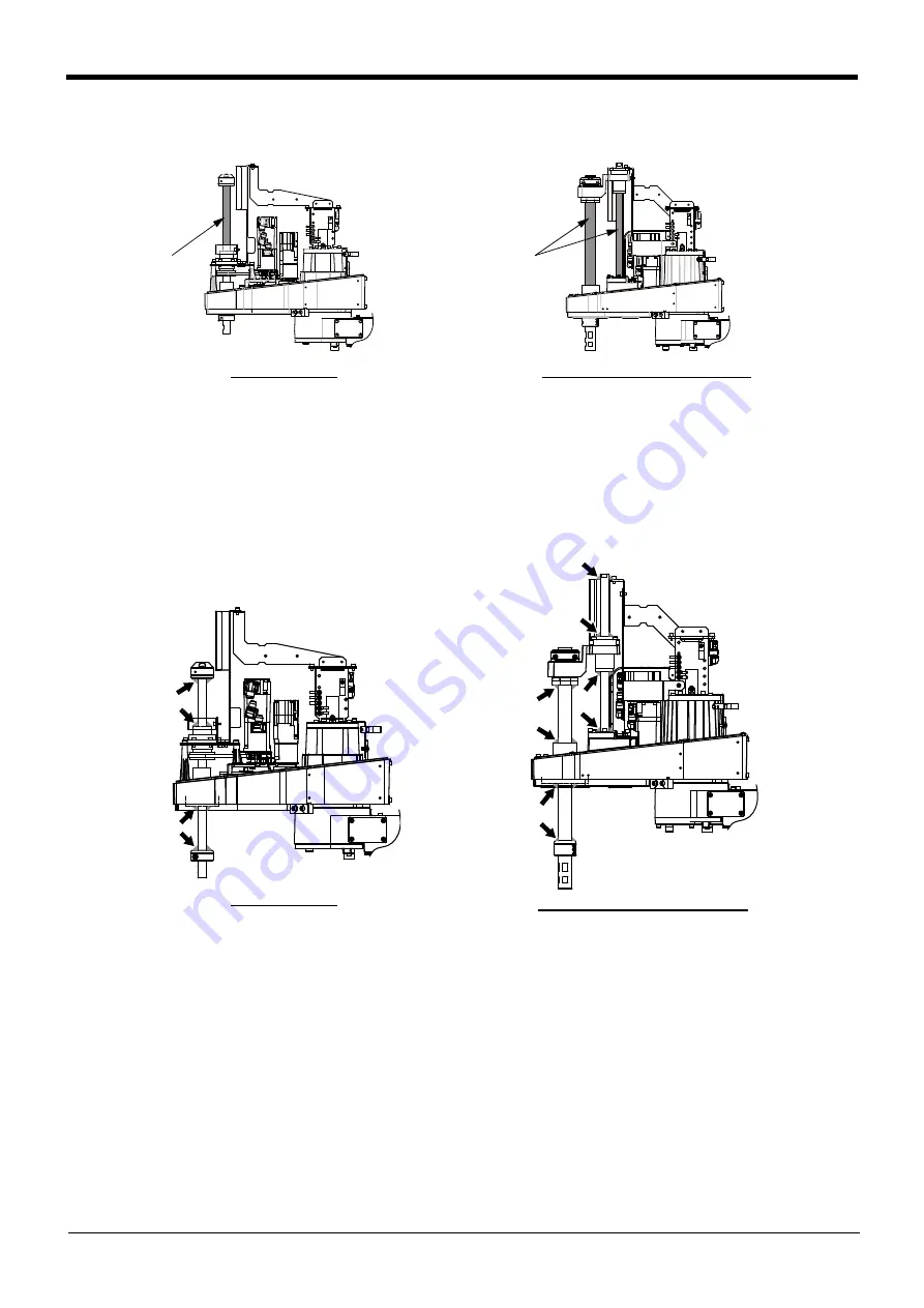
9) Wipe off the grease adhering around the shaft ends or the nuts of the ball spline and the ball screw (indi
-
cated with the arrows below).
When the ball spline and the ball screw are moved with extra grease on them, a large amount of grease is
scattered inside the arm. The grease may reach the timing belt inside the No.2 arm, causing the timing belt
to deteriorate early.
10) Install the No.2 arm cover U as before. Install the bellows as before in the oil mist and clean specification
Note) Sealant is applied to the installation surface of cover in the oil mist and clean specification models.
Be sure to replace the sealant if it has been dislocated and bent or crushed and does not return to
its original shape. If the sealant is required to be replaced, contact the dealer.
Applying grease to shaft is completed.
RH-6FRH/12FRH/20FRH series
RH-3FRH series
Grease
application
area
Grease
application
area
RH-6FRH/12FRH/20FRH series
RH-3FRH series


