3-58
Installing the solenoid valve set
3Installing the option devices
(1) RV-4F/7F series, RV-7FLL
This paragraph explains how to install the solenoid valve set (1F-VD0*-02/1F-VD0*E-02) to RV-4F/7F series
and RV-7FLL robots.
Turn the controller’s power OFF before this installing operation.
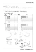
Moreover, please prepare the following furnished accessory.
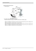
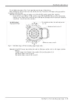
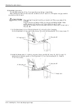
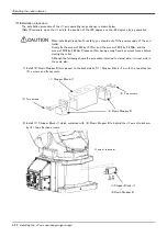
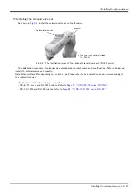
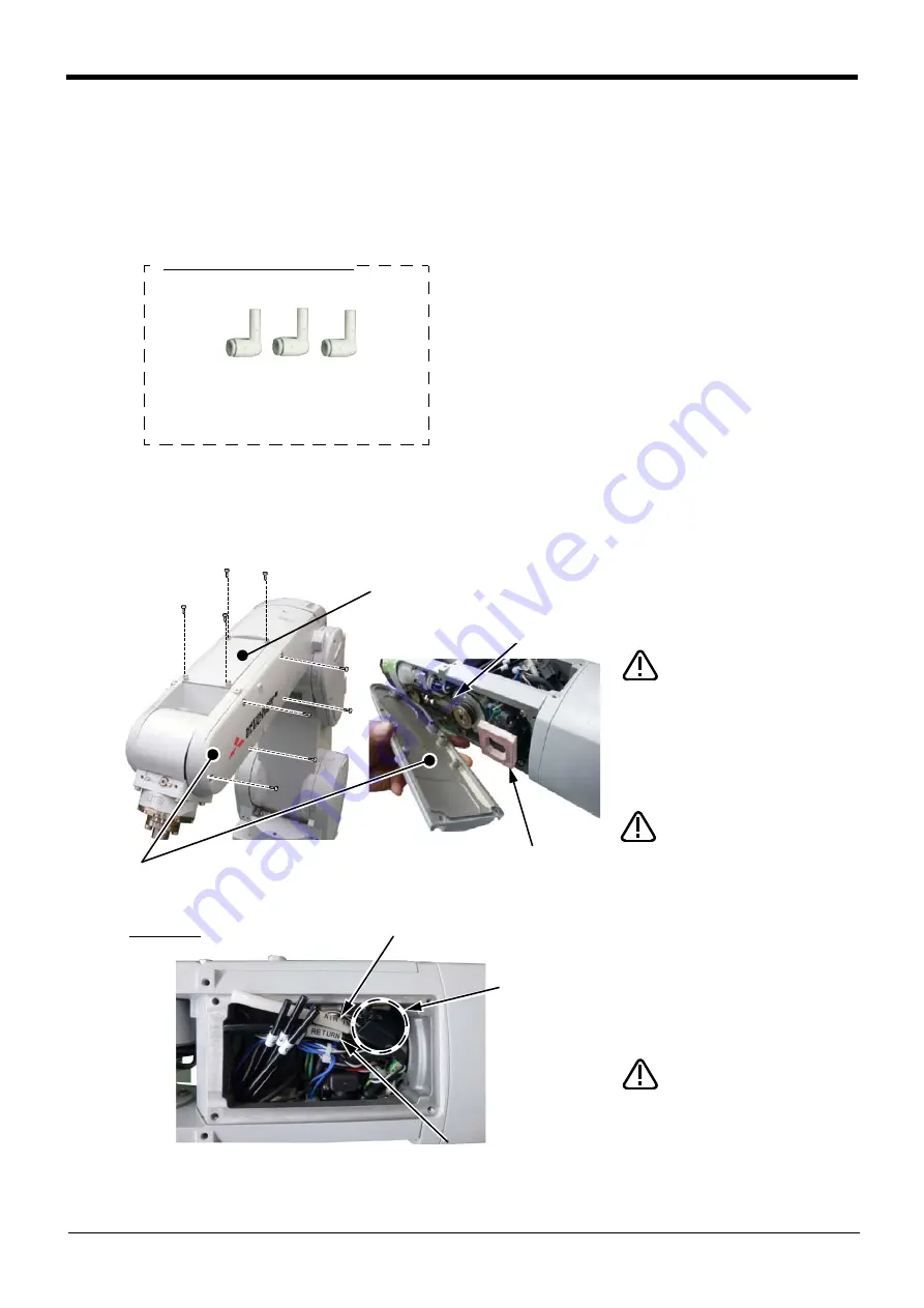
1) Loosen the fixing screws (M4x12) and detach the No.2 arm cover U (forearm upside) and the No.2 arm cover
L (forearm side face).
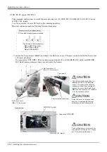
The connectors (GR1, GR2), φ4 secondary piping air hoses (4), and the AIR IN (φ6, white) and RETURN
(φ6, black) primary piping air hoses are set inside the forearm.
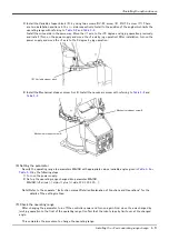
* Three elbow couplings are attached.
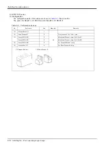
Solenoid-valve set attachments
<Type name of elbow coupling>
Maker: SMC Corporation
Name: Plug-in elbow
Model: KQ2L06-99A
No.2 arm cover U
(M4 x 12, (four screws)
Thermal conductive sheet
After the cover is removed, take
care not to damage the thermal
conductive sheet or timing belt.
CAUTION
Timing belt
Forearm top
AIR IN (φ6, white)
Connector (GR1, GR2)
RETURN (φ6, black)
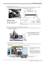
Take sufficient care to prevent for
-
eign matters (cut chips of air hoses,
etc.) from entering the robot.
CAUTION
No.2 arm cover L
(M4 x 12, five screws)
The thermal conductive sheet is
adhered closely to the No.2 arm
cover L. To prevent the thermal
conductive sheet from coming off,
detach the cover slowly and firmly.
When the sheet comes off, reattach
it to the original position.
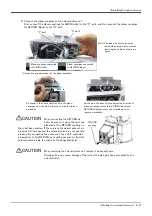
CAUTION

