background image

3-68   

Installing the hand input cable

3Installing the option devices

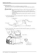
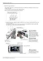
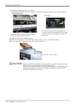
4) Fixes the cable clamp box securely by the fixing screws as before. Installs carefully so that the cable may not 

be inserted.

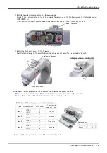
This completes installing the cable clamp box. Pin assign of the hand input cable is shown in 

Table 3-8

.

Table 3-8 : Pin assign of hand input cable

Color

Connector 

Note1)

Note1)The connector shows the connector name connected to the robot-arm side.

Pin number: names

Color

Connector 

Note1) 

Pin number: names

Purple

OP1

A1: HC1

Yellow

OP3

A1: +24V

Brown

A2: HC2

Green

A2: +24G (RG)

Blue

A3: HC3

-

Reserved

Black

A4: HC4

-

Reserved

Red

B1: HC5

White

B2: HC6

Gray

B3: HC7

Pink

B4: HC8

* The figure is the example to which the J4 axis was 

moved to upside down position by jog operation.

When you install the cable clamp 
box, be careful to not put the 
cable between the cable clamp 

box and arm. If the cable is inserted, it will become the cause 
that the cable be broken.


 CAUTION

Fixing screws
(Three places)

When this cable is connected to 
the robot the power supply is 

applied to the end of this cable. The end of the cable is free at 
factory shipping. so, if the tool side is not connected it may be 
cause of the trouble such as broken the fuse by short circuit. 
Before connecting to the robot, customer should check 
whether or not the cable tip has been properly treated.


 CAUTION

Summary of Contents for RV-13FM-SE Series

Page 1: ...Mitsubishi Industrial Robot RV 4 7 13 20FM SE Series INSTRUCTION MANUAL ROBOT ARM SETUP MAINTENANCE BFP A3324 C ...

Page 2: ......

Page 3: ...s on the start switch etc This also applies to maintenance work with the power source turned ON Indication of teaching work in progress Provide a fence or enclosure during operation to prevent contact of the operator and robot Installation of safety fence Establish a set signaling method to the related operators for starting work and follow this method Signaling of operation start As a principle t...

Page 4: ...nd securely grasp the workpiece Failure to observe this could lead to personal injuries or damage if the object comes off or flies off during operation Securely ground the robot and controller Failure to observe this could lead to malfunctioning by noise or to electric shock accidents Indicate the operation state during robot operation Failure to indicate the state could lead to operators approach...

Page 5: ... from the tip of SSCNET III connectors or SSCNET III cables Eye discomfort may be felt if exposed to the light Reference SSCNET III employs a Class 1 or equivalent light source as specified in JIS C 6802 and IEC60825 1 domestic standards in Japan Attach the cap to the SSCNET III connector after disconnecting the SSCNET III cable If the cap is not attached dirt or dust may adhere to the connector p...

Page 6: ... pins with the following numbers Crimping caulking is recommended to connect the ACIN terminals For single phase 1 and 3 For three phase 1 2 and 3 Refer to the figure above and connect the cable from the secondary side of the earth leakage breaker 5 Connect this ACIN connector to the ACIN connector on the front of the controller 6 Connect the grounding cable to the PE terminal M4 screw 7 Connect t...

Page 7: ...thod were added The description of the setting range of ABS origin method was added The caution in lubrication was added The corporate logo mark of illustrations in this manual was changed In recommended grease gun CH 400 was deleted and KH 120 was added 2015 02 09 BFP A3324 C The special hexagon flange bolts are also used for SE1502 model Belt type of J3 and J4 axis timing belt of RV 4F series wa...

Page 8: ...cates it as RV 7F series RV 7FLL 1 RV 13F 13FL series 1 RV 20F series 1 1 Indicates it as RV 13F series for a general name of these robots No part of this manual may be reproduced by any means or in any form without prior consent from Mitsubishi The details of this manual are subject to change without notice The information contained in this document has been written to be accurate as much as poss...

Page 9: ...origin data input method 2 20 1 Confirming the origin data 2 20 2 Turning ON the control power 2 20 3 Preparing the T B 2 21 4 Selecting the origin setting method 2 22 5 Inputting the origin data 2 23 6 Installing the CONBOX cover 2 24 2 4 Confirming the operation 2 25 1 JOINT jog operation 2 29 2 XYZ jog operation 2 31 3 TOOL jog operation 2 33 4 3 axis XYZ jog operation 2 35 5 CYLNDER jog operat...

Page 10: ...ent of J4 axis timing belt 5 88 5 Inspection maintenance and replacement of J4 axis timing belt For RV 13F series 5 89 6 Inspection maintenance and replacement of J5 axis timing belt 5 90 7 Inspection maintenance and replacement of J6 axis timing belt 5 92 8 Timing belt tension 5 94 5 3 4 Lubrication 5 95 1 Lubrication position and specifications 5 95 2 Lubrication method 5 97 5 3 5 Replacing the ...

Page 11: ...lained Explains the procedures required to operate the robot arm unpacking transportation installation confirmation of operation and the maintenance and inspection procedures Explains the procedures required to operate the controller unpacking transportation installation confirmation of operation basic operation from creating the program to auto matic operation and the maintenance and inspection p...

Page 12: ...ndling is mistaken Always observe these precau tions to safely use the robot Precaution indicating cases where the operator could be subject to fatalities or serious injuries if handling is mistaken Always observe these precautions to safely use the robot Precaution indicating cases where operator could be subject to injury or physical damage could occur if handling is mistaken Always observe thes...

Page 13: ...g work This also applies to maintenance work with the power source turned ON Setting of emergency stop switch During teaching work place a sign indicating that teaching work is in progress on the start switch etc This also applies to maintenance work with the power source turned ON Indication of teaching work in progress Provide a fence or enclosure during operation to prevent contact of the opera...

Page 14: ...ould lead to personal injuries or damage if the object comes off or flies off during operation Securely ground the robot and controller Failure to observe this could lead to malfunctioning by noise or to electric shock accidents Indicate the operation state during robot operation Failure to indicate the state could lead to operators approaching the robot or to incorrect operation When carrying out...

Page 15: ...light Reference SSCNET III employs a Class 1 or equivalent light source as specified in JIS C 6802 and IEC60825 1 domestic standards in Japan Do not remove the SSCNET III cable while power is supplied to the controller Do not look directly at light emitted from the tip of SSCNET III connectors or SSCNET III cables Eye discomfort may be felt if exposed to the light Reference SSCNET III employs a Cl...

Page 16: ...pension fitting installation bolt M6 x 20 6 pcs 9 Plain washer for suspension fitting installa tion bolt For M6 6 pcs 10 Eye bolt M10 4 pcs 11 Nut for eye bolt For M10 4 pcs 12 Fixing plate 1 set 13 Fixing plate installation bolt M15 x 12 4 pcs 14 Plain washer for fixing plate For M5 4 pcs RV 7F series 1 Robot arm RV 7FM SExxxx RV 7FLM SExxxx Each 1 unit SExxxx means the following SExx01 Chemical ...

Page 17: ...pecifications 2 Guarantee card 1 copy 3 Installation bolts M12 x 55 4 pcs For robot arm installation 4 Spring washer for installation bolts For M12 4 pcs 5 Plain washer for installation bolts For M12 4 pcs 6 Grease nipple WA 110 3 pcs WA 610 4 pcs 7 Suspension fitting 2 sets 8 Suspension fitting installation bolt M10 x 45 4 pcs 9 Plain washer for suspension fitting installa tion bolt For M10 4 pcs...

Page 18: ... at an unstable place The unpacking process is shown below 1 Using a knife etc slit the tape 1 fixing the upper lid 2 of the cardboard box Fig 2 1 a 2 Pull the upper lid 2 of the cardboard box off with both hands Fig 2 1 b 3 Remove the hexagon socket bolts 3 four positions connecting the sleeper and the base unit Fig 2 1 c 4 This completes the unpacking 上ブタ a b c 引き抜く テープ フォークリフトの爪 挿入口 ロボット本体 CAUT...

Page 19: ...series Fig 2 3 Transportation procedure transporting with a crane RV 13F series Front Side Wire Fixing plate Suspension fitting Mass RV 4F Approx 39kg RV 4FL Approx 41kg RV 7F Approx 65kg RV 7FL Approx 67kg Note The figure is the RV 4 F series The shape and installation screw of the suspension fitting of RV 7F series differ RV 4F RV 7F series Front Side Wire Fixing plate Suspension fitting Mass RV...

Page 20: ...te At this time make sure that the wires etc do not interfere with the robot arm or covers Always place cloth etc at interfering places 3 When transferring to the installation place take care not to apply vibration or impact 4 After installing at the installation place remove the above suspension fittings 5 Always follow the above procedures and methods to transport the robot for secondary transpo...

Page 21: ...he robot moves 4 When installing use a common table to prevent the position of the devices and jigs subject to robot work from deviating 5 The installation surface must have sufficient strength to withstand the arm reaction during operation and resistance against deformation and vibration caused by the static dynamic load of the robot arm and peripheral devices etc 6 Remove the fixing plates after...

Page 22: ... exchange the backup battery in the rear side and also space for J1 axis belt in the right side And don t install the robot arm in the position where direct rays or the heat of lighting hits The skin temperature of the robot arm may rise and the error may occur Item Unit Value RV 4F series RV 7F series RV 7FLL RV 13F series RV 20F Falling moment ML N m 410 900 2 060 Twist moment MT N m 400 900 2 0...

Page 23: ...s possi ble and the length of the grounding wire should be short Fig 2 5 Grounding methods 2 Grounding procedures 1 Prepare the grounding cable AWG 11 4 2mm2 or more and robot side installation screw and washer 2 If there is rust or paint on the grounding screw section A remove it with a file etc 3 Connect the grounding cable to the grounding screw section Fig 2 6 Connecting the grounding cable Ro...

Page 24: ...Although the figure is RH 6FH also in other robots with same connector type the connection method is the same 3 After connecting the connector insert the hook attached to the connector on the machine cable side to the rear of the projection of the robot arm connector to fix securely in place This complete the connection of machine cable CN1 CN2 ロボット本体 ベース部背面 ラッチ ラッチ モータ信号ケーブル モータパワーケーブル モータパワー CN1...

Page 25: ...ble is pulled with force or bent excessively wires could break or the connector could be damaged Connect the machine cable at the place without the effect of the dust or oil mist Please keep the dust and oil mist from being applied to of the robot arm connector section in the condition that the machine cable is removed Since it becomes the cause of failure Please be careful not to catch the hand a...

Page 26: ...trative purposes only Refer to Table 2 3 for packing pose of actual products Pass into the opening AMP1 AMP2 CN2 Machine cables Controller side Battery fixing plate Note1 Note2 CON cover Eight fixing screws Robot arm side Cable clamp fixing plate Two plate with four screws each Two fixing screws Connection condition Table 2 3 The packing pose for each type reference Unit degree Axis RV 4F RV 4FL R...

Page 27: ...with the four screws respectively e Install the battery fixing plate securely as before Be careful not to insert the cable f Install the CONBOX cover securely as before Be careful not to insert the cable 3 Connect the machine cable to the corresponding connector of the controller Connects the connector CN1 AMP1 AMP2 BRK CN2 surely Fix the two fixing screws securely respectively Tighten the fixing ...

Page 28: ...do not bend it too much It becomes the breaking of a wire of the cable and the cause of breakage of the connector Please installing and removing so that stress does not start the cable with the connector itself 1 CR750 controller Explain the installation method of T B below 1 Check that the POWER power supply switch of the robot controller is OFF 2 Connects T B connector to the robot controller Us...

Page 29: ...llation of T B is finished A部 ティーチングボックス T B T B接続用コネクタ A部詳細 手回しロック 2箇所 Controller T B connector Teaching pendant Details of the A section A Hand lock Two places T B connector Note Although the figure is RV 4F 7F series controller and RV 13F series is also the same If error C0150 occurs At the time of the first power supply injection error C0150 the serial number of the robot arm has not been set ...

Page 30: ... install remove the cover with the controller control power turned OFF Failure to do so could lead to physical damage or personal injury should the robot start moving due to incorrect operations 2 Turning ON the control power Confirm that there are no operators near the robot before turning the power ON 1 Turn the controller POWER switch ON The CR750 controller turns ON the front power switch The ...

Page 31: ...e menu selection screen will appear The following operations are carried out with the T B 下 ENABLE ランプ点灯 上 DISABLE T B背面 Up Disable Down Enable Lighting MODE MANUAL AUTOMATIC Operating from the T B Always set the mode of the controller to MAMNUAL and then set the T B ENABLE switch to ENABLE When the T B is valid only operations from the T B are possible Operations from the controller or external s...

Page 32: ... BRK 5 SET INIT 6 ENHANCED CLOSE 123 ORIGIN BRAKE 1 ORIGIN 2 BRAKE CLOSE 123 ORIGIN 1 DATA 2 MECH 3 TOOL 4 ABS 5 USER CLOSE 123 ORIGIN DATA D J1 J2 J3 J4 J5 J6 J7 J8 CLOSE 123 Selecting a menu The menu can be selected with one of the following methods A Press the numeral key for the No of the item to be selected B Using the and keys etc move the cursor to the item to be selected and then press the...

Page 33: ...the key five times will be set Press the key once and advance the cursor Press the key twice input and press the PQRS key four times input S Press the CHARACTER key and set to the numeral input mode Condition that 123 was displayed under the screen Press the 2 key input 2 and press the 9 key input 9 V S29 will appear at the D data on the teaching pendant screen 3 Press the key and move the cursor ...

Page 34: ...V S29 J1 06DTYY J2 2 HL9X J3 1CP55V J4 T6 MSY J5 Z21J Z J6 A12 Z0 J7 J8 CLOSE ABC ORIGIN DATA CHANGE TO ORIGIN OK No 123 Yes Moving the cursor Press the and keys Inputting characters Press the CHARACTER key and set to the character input mode Condition that ABC was displayed under the screen The displayed character is scrolled each time at pressing the key How to input symbols The symbol is alloca...

Page 35: ...pressed To check whether the origin of the robot deviates move the robot arm to the posi tion where the ABS marks align each other and check the displayed joint coordi nates of the position For the details of the ABS mark position and the joint coordinates refer to Page 104 5 6 Resetting the origin and Page 119 5 6 2 ABS origin method Confirm that the origin has been set If the origin has not been...

Page 36: ...s J3 axis J4 axis J5 axis J6 axis Each axis moves independently X Y Z Z Y X ツ ー ル 長 X Y Z 制御点 While maintaining the flange surface posture the axis moves straight along the base coordinate system The robot maintains the flange surface posture Also while maintaining the flange surface position the flange surface posture changes Control point Tool length ...

Page 37: ...g the flange surface position the flange surface posture changes Control point Tool length X Y Z Z Y X J4軸 J5軸 J6軸 ツ ー ル 長 制御点 Control point Tool length The axis moves straight along the base coordinate system At this time the flange surface posture is not maintained Also the flange surface posture changes The flange surface position does not change at this time It is effective to change the postu...

Page 38: ... l l e n g t h Vertical Radius Arc While maintaining the flange surface posture the axis moves straight along the work coordinate system Also while maintaining the flange surface position the flange surface posture changes When the controller software version is R5 F Q series S5 F D series or later jog operation around the work coordinates system is available EX T jog In this jog operation when th...

Page 39: ... if the OVRD key is pressed it will go down The current setting speed is displayed on screen upper right and STATUS NUMBER of the controller Set the override to 10 here for confirmation work When the X J1 keys are pressed the J1 axis will rotate in the plus direction When the X J1 keys are pressed rotate in the minus direction When the Y J2 keys are pressed the J2 axis will rotate in the plus dire...

Page 40: ...otate in the minus direction When the C J6 keys are pressed the J6 axis will rotate in the plus direction When the C J6 keys are pressed rotate in the minus direction When the robot is in the transportation posture The axes may be outside the movement area Move these axes toward the inner side of the movement area J3軸回転 J3 axis jog operation J3 axis J4軸 J5軸 J6軸 SPACE J4 J5 and J6 axis jog operatio...

Page 41: ... When the X J1 keys are pressed move along the minus direction When the Y J2 keys are pressed the robot will move along the Y axis plus direction When the Y J2 keys are pressed move along the minus direction When the Z J3 keys are pressed the robot will move along the Z axis plus direction When the Z J3 keys are pressed move along the minus direction Select XYZ jog mode Set jog speed Setting the s...

Page 42: ...oes not move If it is going to move the robot across the operation range the buzzer of T B sounds and the robot does not move In this case please move to the counter direction The control point does not change Changing the flange surface posture X Y Z Z Y X ツ ー ル 長 X Y Z 制御点 SPACE Tool length Control point When alarm No 5150 occurs If alarm No 5150 ORIGIN NOT SET occurs the origin has not been set...

Page 43: ...ys are pressed move along the minus direction When the Y J2 keys are pressed the robot will move along the Y axis plus direction of the tool coordinate system When the Y J2 keys are pressed move along the minus direction When the Z J3 keys are pressed the robot will move along the Z axis plus direction of the tool coordinate system When the Z J3 keys are pressed move along the minus direction Sele...

Page 44: ... minus direction If the buzzer of T B sounds and the robot does not move If it is going to move the robot across the operation range the buzzer of T B sounds and the robot does not move In this case please move to the counter direction X Z ツ ー ル 長 Y SPACE Changing the flange surface posture The control point does not change Tool length When alarm No 5150 occurs If alarm No 5150 ORIGIN NOT SET occu...

Page 45: ...STATUS NUMBER of the controller Set the override to 10 here for confirmation work When the X J1 keys are pressed the robot will move along the X axis plus direction When the X J1 keys are pressed move along the minus direction When the Y J2 keys are pressed the robot will move along the Y axis plus direction When the Y J2 keys are pressed move along the minus direction When the Z J3 keys are press...

Page 46: ...move simultaneously except J4 and J6 When the B J5 keys are pressed rotate in the minus direction When the C J6 keys are pressed the J6 axis will rotate in the plus direction When the C J6 keys are pressed rotate in the minus direction The flange surface end axis posture cannot be maintained with 3 axis XYZ jog With 3 axis XYZ jog the flange surface end axis posture orientation is not maintained w...

Page 47: ...k Assuming that the current position is on an arc centering on the Z axis the robot moves along that arc When the X J1 keys are pressed the robot will expand in the radial direction When the X J1 keys are pressed contract in the radial direction When the Y J2 keys are pressed the robot will move along the arc in the plus direction When the Y J2 keys are pressed move in the minus direction When the...

Page 48: ... Y axis will rotate in the plus direction When the B J5 keys are pressed rotate in the minus direction When the C J6 keys are pressed the Z axis will rotate in the plus direction When the C J6 keys are pressed rotates in the minus direction Changing the flange surface posture X Y Z Z Y X ツ ー ル 長 X Y Z SPACE 制御点 Control point Tool length The flange position does not change This is the same as the A...

Page 49: ...tem teaching point The setting definition method of the work coordinates system is shown in the following 1 Select 6 ENHANCED screen on the MENU screen Zw Xw Yw Z Y X Robot coordinates system Work WY WO WX work coordinates Notes The figure is the example of RV 6SD but other types are the same The jogging movement based on this work is possible Teaching point WO Work coordinates system origin WX Po...

Page 50: ...esponding to TEACH F1 The confirmation screen is displayed The screen shows the coordinate value of the origin WO of the work coordinates number 1 EMHANCED 1 SQ DIRECT 2 WORK COORD CLOSE 123 WORK COORD WORK NUMBER 1 TEACHING POINT WO X 0 00 Y 0 00 Z 0 00 123 TEACH WX WY DEFINE WORK COORD WORK NUMBER 1 TEACHING POINT WO X 0 00 Y 0 00 Z 0 00 123 W JUMP W GRID CLOSE WORK JUMP CHOOSE ONE OF THE WORK N...

Page 51: ...d re teach the three points This work coordinate data is registered into parameter WKnCORD n means the work coordinates numbers 1 8 If the function key corresponding to CLOSE is pressed it will return to the previous screen 6 Finishing of setting the work coordinates Press the FUNCTION keys and display CLOSE function Press the function key corresponding to CLOSE Returns to the MENU screen WORK COO...

Page 52: ...ys confirm that the number of the target work coordinates system is displayed correctly Display of W1 W8 at the upper right of the screen If mistaken the robot will move in the direction which is not meant and will cause the damage and the personal injuries Whenever it presses the key of OVRD Upper arrow the override goes up Conversely if the OVRD Lower arrow key is pressed it will go down The cur...

Page 53: ...ressed the robot will move along the Z axis Zw plus direction on the work coordinates system When the Z J3 keys are pressed Move along the minus direction When the X Y or Z keys are used the operation is the same in the WORK jog and the Ex T jog modes WORK jog operation mode Conventional WORK jog Ex T jog Parameters WKnJOGMD n is 1 to8 set ting 0 initial value 1 XYZ key operation Moves along each ...

Page 54: ...dinate system When the B J5 keys are pressed rotate in the minus direction When the C J6 keys are pressed the Z axis will rotate in the plus direction of the work coordinate system When the C J6 keys are pressed rotate in the minus direction X Y Z Z Y X ツール長 Xw Yw Zw Zw Xw Yw Yw Xw Zw Changing the flange surface posture 1 Work jog mode The position of the control point does not change Change the d...

Page 55: ...d each axes of work coordinates system Ex T coordinates system When the A J4 or the A J4 key is pressed the control point rotates around the Xw axis When the B J5 or the B J5 key is pressed the control point rotates around the Yw axis When the C J6 or the C J6 key is pressed the control point rotates around the Zw axis Work coordinates system Ex T coordinates system Control point Work coordinates ...

Page 56: ...n Tool length The default tool length is 0mm and the control point is the center of the end axis After installing the hand set the correct tool length in the parameters Refer to the separate manual Detailed Explanation of Functions and Operations for details ...

Page 57: ...ss kg Remarks RV 4F series 1 Stopper plate 2 1 1 One piece each for side side 2 Fixing block A 2 One piece each for side side 3 Fixing block B 1 side 4 Fixing block C 1 side 5 Variable stopper block 2 One piece each for side side 6 Screw M10x20 2 Use for mechanical stopper screw A and B 7 Screw M6x25 2 For fixing 8 Screw M6x20 16 For fixing RV 7F series 1 Stopper plate 2 1 1 One piece each for sid...

Page 58: ...e simultaneously cannot be used The other combination can be set up Parameter MEJAR setting value 240 30 73 103 146 minus side 240 30 73 103 146 Variable stopper block angle 33 76 106 149 Variable stopper block position Note1 d c d c Mechanical stopper screw B Note2 Use Disuse Note3 Parameter MEJAR setting value 240 30 73 103 146 Item Standard Changeable angle combination of side side Unit Degree ...

Page 59: ...5Nm Please confirm having surely fixed by correct torque before moving the robot Although the following shows the procedure installed to plus side minus side is the same also Fig 3 1 Installation image of J1axis operating range change option Example In the RV 7F series when limiting the side to 35 degree and the side to 141 degree install as following Variable stopper block Installs in the positio...

Page 60: ...ew of M10 by 26 5Nm Please confirm having surely fixed by correct torque before moving the robot Although the following shows the procedure installed to plus side minus side is the same also 1 Fix the Fixing block A 2 and the Fixing block B 3 to the robot arm as temporary Fix the Fixing block A 2 by using the two screws 8 and fix the Fixing block B 3 by using a screw 7 2 Install the Stopper plate ...

Page 61: ...ll the necessary screw with referring to Table 3 2 and Table 3 3 4 Setting the parameter Specify the operating range to parameters MEJAR with appropriate values variable angles given in Table 3 2 or Table 3 3 by the following steps 1 Turn on the power supply 2 Set up the operating range changed into parameter MEJAR MEJAR J1 minus side J1 plus side Note Refer to the separate Instruction manual Deta...

Page 62: ...xx01 is 1F DH 08 and for SExx02 is 1F DH 05J1 Table 3 4 Configuration devices No Part name Qty Mass kg Remarks 1 Stopper Block J1 1 0 3 2 Resin Stopper B 2 One piece each for side side 3 Screw M12 25 2 Mechanical Stopper screw For SExx01 Screw M12 20 2 Mechanical Stopper screw For SExx02 4 Screw M10 40 2 For Stopper Block J1 fixing 5 Screw M4 12 4 For Resin Stopper B fixing 1 Stopper Block J1 2 Re...

Page 63: ... of J1axis operating range change option RV 13F series Example In the RV 13F series when limiting side to 32 5 degree and side to 122 5 degree install the Mechanical Stopper screw in the position of A and C Item Standard Changeable angle plus side 190 30 120 Mechanical Stopper screw position Note1 Note1 Symbol A D in the Table 3 5 is related with the symbol of Fig 3 2 Installation image of J1axis ...

Page 64: ...m and the screw of M10 by 26 5Nm and the screw of M12 by 26 5Nm Please confirm having surely fixed by correct torque before moving the robot Although the following shows the procedure installed to plus side minus side is the same also 1 Install 2 Resin Stopper B two pieces to the both sides of 1 Stopper Block J1 in with the two attached 5 screws and fix securely 2 Install 1 Stopper Block J1 which ...

Page 65: ...e power supply and move the J1 axis by jog operation 4 Install the 3 Mechanical Stopper screw Install the 3 attached Mechanical Stopper screw to the needed point with referring to Table 3 5 and Fig 3 2 1 Stopper Block J1 2 Resin Stopper B Mechanical Stopper screw B Mechanical Stopper screw A 1 Stopper Block J1 2 Resin Stopper B Mechanical Stopper screw D Mechanical Stopper screw C Back side ...

Page 66: ... into parameter MEJAR MEJAR J1 minus side J1 plus side Note Refer to the separate Instruction manual Detailed Explanation of Functions and Operations for the details of the setting method 5 Check the operating range After changing the parameter turn off the controller power and turn on again And move the axis changed by joint jog operation to the limit of the operating range Confirm that the robot...

Page 67: ...depends on robot series and specifications Refer to below and install the solenoid valve set properly Installation method differ depending on a robot s type Please refer to the explanation section corresponding to the robot which uses Explanation section for each type of robot RV 4F 7F series and RV 7FLL robots Refer to Page 58 1 RV 4F 7F series RV 7FLL RV 13F 13FL and RV 20F robots Refer to Page ...

Page 68: ... set inside the forearm Three elbow couplings are attached Solenoid valve set attachments Type name of elbow coupling Maker SMC Corporation Name Plug in elbow Model KQ2L06 99A No 2 arm cover U M4 x 12 four screws Thermal conductive sheet After the cover is removed take care not to damage the thermal conductive sheet or timing belt CAUTION Timing belt Forearm top AIR IN φ6 white Connector GR1 GR2 R...

Page 69: ...n and adjust Cutting dimension guide Rubber sheet Union band AIR IN white A mm φ6 primary piping air hose RETURN black B mm Cutting dimension guide A B Unit mm Robot Dimension A AIR IN Dimension B RETURN RV 4F 60 35 RV 4FL 7F 7FL 7FLL series 70 45 Take sufficient care to prevent for eign matters cut chips of air hoses etc from entering the robot CAUTION Attach the elbow couplings to the AIR IN whi...

Page 70: ...in a figure If that is not right store as shown in a figure b Connects the hand output cable inside the forearm GR1 and GR2 to the connectors of the solenoid valve set Note In the solenoid valve set of one set or two sets connects only connector GR1 c Store the connected connectors in the positions shown in the figure below Solenoid valve set Wiring position Connect with the same names GR1 connect...

Page 71: ...lenoid valve to improve workability Push in Connection and adjustment of the elbow couplings When connecting the RETURN air hose be sure to remove the dust cap attached at the RETURN coupling on the robot base section If the cap is not removed exhaust air pressure will increase and the solenoid valve may not operate properly By connecting the exhaust air hose φ6 customer preparation to this RETURN...

Page 72: ...valve cover be broken And if the air hose is put or it breaks it becomes the cause that the solenoid valve operation is abnormal The solenoid valve is installed to the shaded area To prevent cables from being pinched push the cables into the forearm and avoid placing any cable on the shaded area Forearm top Visually check that the cables and air hoses are not pinched and the air hoses are not bent...

Page 73: ...et 9 Connect the tool prepared by the customer with solenoid valve port A and B When you use the standard specification robot please prepare the air hoses for connection Table 3 6 shows the relation between hand condition and port number This completes the procedure to install the solenoid valve set Solenoid valve set Forearm No 2 arm cover L Solenoid valve set A Enlarged view of section A Plugs T...

Page 74: ...ng of the sole noid valve set and connects RETURN black to R port coupling of the solenoid valve set The AIR IN white air hose is connected with the AIR IN coupling of the robot arm base rear and the RETURN black air hose is connected with the RETURN coupling Because the long length air hoses are equipped please cut and connect it to the suitable length If that is not right the air hose breaks wit...

Page 75: ...cause that the cable be broken And if the air hose is put or it breaks it becomes the cause that the solenoid valve operation is abnormal Confirms having inserted neither the cable nor the air hose and that the air hose has not broken and fix the No 2 arm cover U securely by the original fixing screws Tightening torque 1 39 1 89N m Confirms that the air hose has not broken by removing the No 2 arm...

Page 76: ...hat are not used for the solenoid valve set Table 3 7 shows the relation between hand condition and port number This completes the procedure to install the solenoid valve set Table 3 7 Solenoid valve ports and hand number Hand Hand condition Port number The solenoid valve set in use Hand 1 OPEN 1 One set CLOSE 2 Hand 2 OPEN 3 Two sets CLOSE 4 Hand 3 OPEN 5 Three sets CLOSE 6 Hand 4 OPEN 7 Four set...

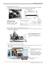
Page 77: ...cable clamp box Uses either one in the cable clamp of both ends a Loosens the threaded cap of the cable clamp and removes the plug Use either one place of both ends b Pass the customer wiring side of cable from inner side Pass the cable with little by little and fix the cable securely by tightening the threaded cap as shown in the following figure 3 Connects the connector inside the forearm OP1 an...

Page 78: ... HC3 Reserved Black A4 HC4 Reserved Red B1 HC5 White B2 HC6 Gray B3 HC7 Pink B4 HC8 The figure is the example to which the J4 axis was moved to upside down position by jog operation When you install the cable clamp box be careful to not put the cable between the cable clamp box and arm If the cable is inserted it will become the cause that the cable be broken CAUTION Fixing screws Three places Whe...

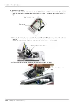
Page 79: ...t hand output cable The installation procedure of the hand output cable is shown below Turn the controller s power OFF before this installing operation 1 Loosen the fixing screws four M4x12 screws of No 2 arm cover U and remove the cover 2 Loosen the fixing screws three M4x16 screws of cable clamp box under forearm and remove it Move the J4 axis in advance to the upside down position by jog operat...

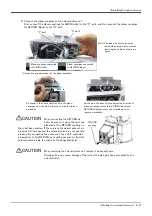
Page 80: ...and GR2 to the connector of the hand output cable Connect with the same names 5 Feed the hand output cable through the cable clamp box Loosens the threaded cap of the cable clamp and removes the plug of the cable clamp box Tip Pass the cable with little by little and pulls out the needed length and fix the cable securely by tightening the threaded cap Hand output cable Feeds through between the mo...

Page 81: ... GR5 Hand output 5 Brown A4 GR2 Hand output 2 White A4 GR6 Hand output 6 Blue B1 GR3 Hand output 3 Gray B1 GR7 Hand output 7 Black B2 GR4 Hand output 4 Pink B2 GR8 Hand output 8 B3 Reserved B3 Reserved B4 Reserved B4 Reserved When you install the cable clamp box be careful to not put the cable between the cable clamp box and arm If the cable is inserted it will become the cause that the cable be b...

Page 82: ...ng screws three M4x16 screws of cable clamp box under forearm and remove the box 2 Connects the connector of robot arm side inside the forearm to the connector of Forearm external wiring set Connect with the same names and keep it into the forearm The connector to connect is shown in Table 3 10 Fig 3 5 Installing the Forearm external wiring set Table 3 10 Cable to pull out and robot side connectio...

Page 83: ...y This completes installing the Forearm external wiring set 2 Installing the Base external wiring set The installation summary of the Base external wiring set is shown in Fig 3 6 Mounts this option instead of the CONBOX cover R 1 Loosen the fixing screws three M4x16 screws of CONBOX cover R and remove the box 2 The connector LAN CNOP1 is in CONBOX cover R The connector is previously attached to th...

Page 84: ...ection connector Grounding process Outlet Name Purpose of use 1F HA01S 02 For SExx01 1F HA01S 01 For SExx02 1 E F1 Force sensor interface CNOP1 Require 2 Reserved 3 LAN Vision sensor controller LAN Not require 4 RIO Reserved CNOP1 Require 1F HA02S 02 For SExx01 1F HA02S 01 For SExx02 1 E F2 Force sensor interface CNOP1 Not require 2 E F1 Reserved CNOP1 Require 3 LAN Vision sensor controller LAN No...

Page 85: ...4 75 4 Basic operations The basic operations from creating the program to automatic operation are explained in section 4 Basic operations in the From Controller Setup to Maintenance manual Refer that manual as necessary ...

Page 86: ...on schedule Guideline for inspection period For one shift 10 Hr day 20 days month 3 months approx 600 Hr For two shifts 15 Hr day 20 days month 3 months approx 1 000 Hr Caution When using two lines the 3 month inspection 6 month inspection and yearly inspection must be carried out when half the time has passed 0 Hr Monthly inspection Monthly inspection 1 000 Hr Monthly inspection 3 month inspectio...

Page 87: ... there any cracks foreign contamination or obstacles on the robot and controller cover Replace with a new part or take remedial measures 7 Is there any abnormality in the pneumatic system Are there any air leaks drain clogging or hose damage Is the air source normal Visual Drain the drainage and remedy the air leaks replace the part 8 Check the exterior for any scratches rusts or separated seals V...

Page 88: ...ny of the bolts or screws on the robot arm loose Securely tighten the bolts 2 Are any of the connector fixing screws or terminal block terminal screws loose Securely tighten the screws Yearly inspection items 1 Replace the backup battery in the robot arm Exchange it referring to Page 99 5 3 5 Replacing the backup battery 2 year inspection items 1 Is the friction at the timing belt teeth severe If ...

Page 89: ...ven by the J2 axis motor 4 and reduction gears 5 3 The rotation of the J3 axis motor 7 arranged in the No 1 arm is conveyed to the reduction gears 9 via the timing belt 8 to rotate the J3 axis 4 The rotation of the J4 axis motor 10 arranged in the elbow is conveyed to the reduction gears 12 via the timing belt 11 to rotate the J4 axis 5 The rotation of the J5 axis motor 13 arranged in the No 2 arm...

Page 90: ...ion gears 11 Reduction gears 8 Reduction gears 7 Timing belt 4 J2 axis motor 6 J3 axis motor 9 J4 axis motor 17 Gear 12 J5 axis motor 13 Timing belt 14 Reduction gears 15 J6 axis motor 3 Reduction gears 21 Reduction gears 2 Timing belt 10 Timing belt Base No 1 arm Elbow No 2 arm 16 Timing belt Shoulder 1 J1 axis motor RV 4F 7F series ...

Page 91: ...series RV 13F series 4 Reduction gears 9 Reduction gears 6 Reduction gears 8 Timing belt 3 J2 axis motor 5 J3 axis motor 7 J4 axis motor 15 Gear 10 J5 axis motor 14 Timing belt 12 Reduction gears 13 J6 axis motor 2 Reduction gears 16 Reduction gears Base No 1 arm Elbow No 2 arm 11 Timing belt Shoulder 1 J1 axis motor ...

Page 92: ...k 1 No 2 arm cover U 2 No 2 arm cover L 3 No 2 arm cover R 4 Elbow cover 5 Cable clamp box 6 No 1 arm cover L 7 No 1 arm cover R 8 No 1 arm cover U 9 Wrist cover 10 J1 motor cover 11 CONBOX cover 12 CONBOX cover R 13 Bottom plate RV 4F 7F series g f a c b d e h RV 13F series 1 No 2 arm cover U 2 No 2 arm cover 3 No 2 arm cover 4 Elbow cover 5 Cable clamp box 7 Wrist cover 6 Shoulder cover 8 CONBOX...

Page 93: ... on one side 6 one side For RV 4FL 7FL series Fix six screws on one side f Hexagon socket head cap screw M4 x 8 4 For RV 4F 7F series 6 For RV 4FL 7FL series g Low head cap screw M3 x 8 4 h Hexagon socket head cap screw M4 x 12 6 i Hexagon socket head cap screw M4 x 8 4 j Hexagon socket head cap screw M4 x 20 3 With attachment seal washer M4 k Flat head screw M4 x 8 5 RV 13F series For SE1101 1501...

Page 94: ... this case change the robot posture with jog operation and then remove the cover 4 When removing the wrist cover move the J5 axis to the position of 90 degrees by jog operation 5 When attaching the cover after maintenance and inspection use the detaching procedure in reverse The part Nos and symbols in Table 5 3 correspond to Fig 5 4 RV 4F 7F series or Fig 5 5 RV 13F series Note1 Hexagon flange bo...

Page 95: ...Please check and adjust and replace if necessary Prepare the sound wave type belt tension gauge in inspection and adjustment of the timing belt The recommen dation gauge is shown below Please prepare by customer Refer to the Page 94 8 Timing belt tension for the tension adjustment value of the timing belt Maker Gates Unitta Asia Company Type U 505 1 Timing belt replacement period The timing belt l...

Page 96: ...with this method Certainly fix two motor plate fixing screws 1 Improper tightening can cause the belt to loosen with vibration If the belt is loosened too much when adjusting the tension causing it to come off the timing pulleys 4 and 5 or if the belt and pulley teeth engagement is deviated the machine system s origin will deviate 5 After adjustment fixes the fixing nut and certainly fix tension a...

Page 97: ...rned to the left will loosen Adjust the belt tension slack to within the range as shown in Fig 5 14 Belt tension If the belt is loosened too much when adjusting the tension causing it to come off the timing pulleys 4 and 5 or if the belt and pulley teeth engagement is deviated the machine system s origin will deviate 4 After adjustment fastens the fixing nut of tension adjustment screw 3 and certa...

Page 98: ...ms indicated in 1 Timing belt replacement period have not occurred with the timing belt 4 Confirm that the belt tension is adjusted to slacken as shown in Fig 5 14 Belt tension Adjusting the J4 axis timing belt 1 Carry out steps 1 and 2 indicated in Inspecting the J4 axis timing belt above 2 Lightly loosen the two motor plate fixing screws 1 Do not loosen too much 3 The nut which is fixing tension...

Page 99: ...d left in the same way 4 Turn the tension adjustment screw 3 and adjust the tension of timing belt 2 When the screw is turned to the right the belt will be stretched and when turned to the left will loosen Adjust the belt tension slack to within the range as shown in Fig 5 14 Belt tension If the belt is loosened too much when adjusting the tension causing it to come off the timing pulleys 4 and 5 ...

Page 100: ...late fixing screws 1 Do not loosen too much 3 The nut which is fixing tension adjustment screw 3 is loosened turn tension adjustment screw 3 and adjust the tension of timing belt 2 When the screw is turned to the right the belt will be stretched and when turned to the left will loosen Adjust the belt tension slack to within the range as shown in Fig 5 14 Belt tension If the belt is loosened too mu...

Page 101: ...the timing belt 2 and timing pulleys 4 and 5 with a felt tip pen as shown in Fig 5 10 RV 4F 7F series RV 7FLL or Fig 5 11 RV 13F 20F so that the engagement of the timing belt 2 and timing pulleys 4 and 5 does not deviate 4 Lightly loosen the three motor plate fixing screws 1 RV 4F 7F series two pc RV 13F series three pc 5 Loosen the nut fixing tension adjustment screw 3 Loosen the tension adjustme...

Page 102: ...he two motor plate fixing screws 1 Do not loosen too much 3 The nut which is fixing tension adjustment screw 3 is loosened turn tension adjustment screw 3 and adjust the tension of timing belt 2 When the screw is turned to the right the belt will be stretched and when turned to the left will loosen Adjust the belt tension slack to within the range as shown in Fig 5 14 Belt tension If the belt is l...

Page 103: ...iming belt 2 and timing pulleys 4 and 5 does not deviate 4 Lightly loosen the two pc motor plate fixing screws 1 Do not loosen too much 5 Loosen the nut fixing tension adjustment screw 3 Loosen the tension adjustment screw 3 and remove the old belt 6 Copy the marks onto the new timing belt Make sure that both belts are tense when making the marks 7 Align the new timing belt with the marks on the t...

Page 104: ...ension N Note1 Note1 The value inside the parenthesis shown in the column of tension of the J1 axis shows the force which pulls the motor plate hook at belt adjustment M g m W mm R S mm New belt Used belt J1 315 3GT 12 2 5 12 85 5 79 7 97 4 80 98 53 1 64 9 53 65 J3 369 3GT 6 2 5 6 118 4 39 2 47 9 26 1 31 9 J4 240 3GT 6 2 5 6 56 4 J5 393 3GT 4 2 5 4 149 8 27 0 33 0 18 0 22 0 J6 270 3GT 4 2 5 4 96 0...

Page 105: ...on specifications for each place are shown in Table 5 4 Refer to the Page 82 5 3 2 Installing removing the cover for the method of removing and installing the cover Fig 5 15 Lubrication positions RV 4F 7F series 2 J2 axis lubrication port 3 J3 axis lubrication port 6 J6 axis lubrication port Reduction gears 7 J6 axis lubrication port Gear 1 J1 axis lubrication port 4 J4 axis lubrication port 5 J5 ...

Page 106: ...uction gears 2g 7 J6 axis gears 1 3g Wrist cover RV 7F series 1 J1 axis reduction gears Grease nipple WA 610 4B No 2 Harmonic Drive Systems Inc 24 000Hr 12g J1 motor cover 2 J2 axis reduction gears 12g 3 J3 axis reduction gears 8g No 1 arm cover L 4 J4 axis reduction gears 4g 5 J5 axis reduction gears 2g 6 J6 axis reduction gears 2g 7 J6 axis gears 1 3g Wrist cover 3 J2 axis waste oil screw A 5 J3...

Page 107: ...t 3 J4 axis lubrication port 4 J5 axis lubrication port 5 J6 axis lubrication port 6 reduction gears and J6 axis lubrication port 7 gear Securely tighten the grease nipple by 4 7 N m to 6 3 N m SExx02 J3 axis lubrication port 3 J4 axis lubrication port 4 J5 axis lubrication port 5 J6 axis lubrication port 6 reduction gears and J6 axis lubrication port 7 gear Securely tighten the grease nipple by 4...

Page 108: ...lls the original screw bolt Tighten the screw bolt by 4 7N m 6 3N m In RV 13F series wind thread sealing tape around the thread of the original screw bolt 2 4 and 5 8 Replace the covers with the removal procedure in reverse 9 If the maintenance forecast function is enable please reset the accumulated data about grease Carries out the resetting operation by RT ToolBox or parameter MFGRST Refer to s...

Page 109: ...d the controller simultaneously Table 5 5 The error about the battery The method of replacing the battery of robot arm is shown below refer to the separate Instruction manual Controller setup basic operation and maintenance about controller s battery About the purchase of the battery refers to Page 102 5 5 Maintenance parts If error 7500 or 112n occurs the program data and other data in the contro...

Page 110: ...ld battery from the holder and disconnect the lead connector 4 Insert the new battery into the holder and connect the lead connector Replace all batteries with new ones at the same time 5 All the batteries should be checked that it has been exchanged newly If the old battery is contained gener ating heat and damaging may occur 6 Install the CONBOX cover 1 as before Be careful so that the cable may...

Page 111: ...aries with their operating conditions and thus with the degree of the equipment s wear and loss of performance As a rule of thumb however it is recommended that overhaul be carried out before the total amount of servo on time reaches the predetermined levels 24 000 hours for the robot body and 36 000 hours for the controller See Fig 5 18 For specific information about parts to be replaced and timi...

Page 112: ... Supplier RV 4F series common 1 AC servo motor J1 J2 axis 2 Mitsubishi Electric 2 J3 axis 1 3 J4 J5 axis 2 4 J6 axis 1 RV 4F Standard arm type 5 Reduction gears J1 J2 axis 2 Mitsubishi Electric 6 J3 axis 1 7 J4 axis 1 8 J5 axis 1 9 J6 axis 1 10 Various seals Application area at the time of shipment 1 RV 4FL Long arm type 11 Reduction gears J1 axis 1 Mitsubishi Electric 12 J2 J3 axis 2 13 J4 axis 1...

Page 113: ...ommon 45 AC servo motor J1 J2 axis 2 Mitsubishi Electric 46 J3 axis 1 47 J4 axis 1 48 J5 axis 1 49 J6 axis 1 RV 13F RV 20F Standard arm type 50 Reduction gears J1 axis 1 Mitsubishi Electric 51 J2 axis 1 52 J3 axis 1 53 J4 axis 1 54 J5 axis 1 55 J6 axis 1 56 Various seals Application area at the time of shipment 1 RV 13FL Long arm type 57 Reduction gears J1 axis 1 Mitsubishi Electric 58 J2 axis 1 5...

Page 114: ...r motor or timing belt After the origin setting is completed move the robot arm to the position where the ABS marks align each other and check that the displayed joint coordinates of the position are correct For the details of the ABS mark position and the joint coordinates refer to Page 119 5 6 2 ABS origin method No Method Explanation Cases when setting the origin is required Remarks 1 Origin da...

Page 115: ... position There are the method of releasing the brake and adjusting with the origin position manually and the method of adjusting with the origin position by jog feed Here explain operation by brake release Then do origin setting operation and set up the origin To ensure safety the brake release procedure described below should always be done by two persons This operation is carried out with the t...

Page 116: ...nt using both hands Align the pinhole of the lower part of the shoulder and the pinhole at the base section feed through the origin jig φ6 into the pinholes and fasten MENU 1 FILE EDIT 2 RUN 3 PARAM 4 ORIGIN BRK 5 SET INIT 6 ENHANCED CLOSE 123 Select ORIGIN BRK Select BRAKE ORIGIN BRAKE 1 ORIGIN 2 BRAKE CLOSE 123 BRAKE J1 0 J2 0 J3 0 J4 0 J5 0 J6 0 J7 0 J8 0 CLOSE 123 REL select axis SPACE Brake r...

Page 117: ...GIN 2 BRAKE CLOSE 123 ORIGIN 1 DATA 2 MECH 3 TOOL 4 ABS 5 USER CLOSE 123 Select TOOL TOOL J1 1 J2 0 J3 0 J4 0 J5 0 J6 0 J7 0 J8 0 CLOSE 123 REL SPACE ORIGIN TOOL CHANGE TO ORIGIN OK No 123 Yes TOOL J1 1 J2 0 J3 0 J4 0 J5 0 J6 0 J7 0 J8 0 CLOSE 123 REL COMPLETED Release the brake Do cursor movement into the parenthesis of each axis by the arrow key The brakes can be released only for the axis for w...

Page 118: ... is released while pressing the key Note In the RV 13F series brake is released in an off and on way because to drop J2 axis slowly 7 With both hands slowly move the J2 axis to minus 107 degree direction RV 4F series to 0 degree direction RV 7F 13F series Align the pinhole of the No 1 arm and the pinhole at the base section feed through the origin jig φ6 into the pinholes and fasten MENU 1 FILE ED...

Page 119: ...ction screen 10 Press the 3 key and display the Tool selec tion screen 11 Input 1 into the J2 axis Set 0 to other axes 12 Press the EXE key and display Confirmation screen 13 Press the F1 key and the origin position is set up 14 Setting of the origin is completed 15 Refer to Page 125 5 6 4 Recording the origin data in this manual and record the origin data on the origin data seal CAUTION CAUTION 0...

Page 120: ...kes are not to be released press the 0 key and display a 0 If the F1 key on the teaching pendant or the enabling switch is detached while the brakes are released the brakes will be work immediately Select the axis of origin setting Do cursor movement into the parenthesis of each axis by the arrow key The origin is set only for the axis for which a 1 is displayed on the screen If the origin is not ...

Page 121: ...s released while pressing the key Note In the RV 13F series brake is released in an off and on way because to drop J2 axis slowly 7 With both hands slowly move the J3 axis to plus 90 degree direction RV 4F series to plus 115 degree direction RV 7F 13F series Align the pinhole of the No 1 arm and the pinhole at the base section feed through the origin jig φ6 into the pinholes and fasten MENU 1 FILE...

Page 122: ...ection screen 10 Press the 3 key and display the Tool selec tion screen 11 Input 1 into the J3 axis Set 0 to other axes 12 Press the EXE key and display Confirmation screen 13 Press the F1 key and the origin position is set up 14 Setting of the origin is completed 15 Refer to Page 125 5 6 4 Recording the origin data in this manual and record the origin data on the origin data seal CAUTION CAUTION ...

Page 123: ...kes are not to be released press the 0 key and display a 0 If the F1 key on the teaching pendant or the enabling switch is detached while the brakes are released the brakes will be work immediately Select the axis of origin setting Do cursor movement into the parenthesis of each axis by the arrow key The origin is set only for the axis for which a 1 is displayed on the screen If the origin is not ...

Page 124: ...h the enabling switch of T B pressed down The brake is released while pressing the key 7 With both hands slowly move the J4 axis to 0 degree direction and align the pinholes of the No 2 arm feed through the origin jig φ6 into the pinholes and fasten 8 Detach the F1 key and work the brake Press the F4 key and return to the origin brake screen MENU 1 FILE EDIT 2 RUN 3 PARAM 4 ORIGIN BRK 5 SET INIT 6...

Page 125: ... 1 J2 0 J3 0 J4 0 J5 0 J6 0 J7 0 J8 0 CLOSE 123 REL 1 0 ORIGIN TOOL CHANGE TO ORIGIN OK No 123 Yes TOOL J1 1 J2 0 J3 0 J4 0 J5 0 J6 0 J7 0 J8 0 CLOSE 123 REL COMPLETED 1 0 Release the brake Do cursor movement into the parenthesis of each axis by the arrow key The brakes can be released only for the axis for which a 1 is displayed on the screen If the brakes are not to be released press the 0 key a...

Page 126: ...ssing the F1 key is kept with the enabling switch of T B pressed down The brake is released while pressing the key 8 Slowly rotate the J5 axis in the direction of plus 90 degree with both hands Align the pinholes of the No 2 arm and wrist feed through the origin jig φ6 into the pinholes and fasten To ensure safety the brake release procedure described below should always be done by two persons Be ...

Page 127: ...is kept with the enabling switch of T B pressed down The brake is released while pressing the key 13 Hold the bolts with hands rotate them slowly and align the ABS mark of the J6 axis with the ABS mark of the wrist area 14 If the ABS mark is aligned detach the F1 key and work the brake 15 Press the F4 key and return to the origin brake screen BRAKE J1 0 J2 0 J3 0 J4 0 J5 1 J6 0 J7 0 J8 0 CLOSE 123...

Page 128: ... 123 REL SPACE ORIGIN BRAKE 1 ORIGIN 2 BRAKE CLOSE 123 ORIGIN 1 DATA 2 MECH 3 TOOL 4 ABS 5 USER CLOSE 123 TOOL COMPLETED J1 0 J2 0 J3 0 J4 0 J5 1 J6 1 J7 0 J8 0 CLOSE 123 REL ORIGIN TOOL CHANGE TO ORIGIN OK No 123 Yes Release the brake Do cursor movement into the parenthesis of each axis by the arrow key The brakes can be released only for the axis for which a 1 is displayed on the screen If the b...

Page 129: ...gin is to be set with jog operation This can be set for all axes simultaneously or each axis independently To align the ABS marks view the robot from the front The deviation between the end points of the two triangular marks must be 1 mm or less The positions where the ABS mark is attached are shown in below Refer to Page 25 2 4 Confirming the operation for details on the jog operation Fig 5 20 AB...

Page 130: ...rk J1 axis J2 axis J3 axis J4 axis J5 axis J6 axis Note Refer to Fig 5 20 for J4 axis mark attachment position The angles of each axis which sets up the ABS origin are shown below J1 axis 0 degrees J2 axis 0 degrees J3 axis 90 degrees J4 axis 0 degrees J5 axis 90 degrees J6 axis 0 degrees Within 1mm side deviation Setting range of ABS mark Within 1mm side deviation ...

Page 131: ...n 3 Press the 4 key and display the ABS selection screen 4 Input 1 into the axis to origin setting Press the EXE key and display Confirmation screen 5 Press the F1 key and the origin position is set up This complete the Origin setting by the ABS method ORIGIN 1 DATA 2 MECH 3 TOOL 4 ABS 5 USER CLOSE 123 MENU 1 FILE EDIT 2 RUN 3 PARAM 4 ORIGIN BRK 5 SET INIT 6 ENHANCED CLOSE 123 ORIGIN BRAKE 1 ORIGI...

Page 132: ...es of the ABS origin by 1 5 or more align the end points of the ABS marks and set the origin using the ABS origin method again When the ABS mark label of the axis other than the J6 axis is peeled off align the pinholes used to set the origin with the jig method The joint coordinates are the same between the ABS origin method and the jig method CAUTION CAUTION ...

Page 133: ...4 Confirming the operation for details on the jog operation Choose the user origin position as the position where it doesn t move by the gravity This position is left as a guideline to position all axes with jog operation when setting the origin again with this method 2 Enter the JOINT jog mode and display the joint coordinates on the teaching pendant screen Record the value of the axis for which ...

Page 134: ...to origin setting Press the EXE key and display Confirmation screen 9 Press the F1 key and the origin position is set up This complete the Origin setting by the User origin method USER J1 1 J2 0 J3 0 J4 0 J5 0 J6 0 J7 0 J8 0 CLOSE 123 REL ORIGIN USER CHANGE TO ORIGIN OK No 123 Yes ...

Page 135: ...bel 1 Confirming the origin data label Remove the CONBOX cover Refer to Page 82 5 3 2 Installing removing the cover and remove the CONBOX cover 2 Confirming the origin data Confirm the value displayed on the teaching pendant s Origin Data Input screen Refer to Page 20 2 3 2 Setting the origin with the origin data input method 5 Inputting the origin data and display the Origin Data Input screen on ...

Page 136: ...ypes of configuration flags are shown below 1 RIGHT LEFT P is center of J5 axis rotation in comparison with the plane through the J1 axis vertical to the ground Fig 6 1 Configuration flag RIGHT LEFT 2 ABOVE BELOW P is center of J5 axis rotation in comparison with the plane through both the J3 and the J2 axis Fig 6 2 Configuration flag ABOVE BELOW 5軸タイプ 6軸タイプ HT LEFT R 心 RIGHT LEFT P J1軸 回転中心 The i...

Page 137: ...which side the J6 axis is in comparison with the plane through both the J4 and the J5 axis Fig 6 3 Configuration flag NONFLIP FLIP J4 axis J6 axis flange surface FLIP NON FILIP FL1 Flag 1 B0000 0000 1 0 NONFLIP FLIP Note B is shows the binary The illustration is an example ...

Page 138: ...Appendix 128 Configuration flag 6Appendix ...

Page 139: ......

Page 140: ...ORKS 5 1 14 YADA MINAMI HIGASHI KU NAGOYA 461 8670 JAPAN Authorised representative MITSUBISHI ELECTRIC EUROPE B V GERMANY Gothaer Str 8 40880 Ratingen P O Box 1548 40835 Ratingen Germany Feb 2015 MEE Printed in Japan on recycled paper Specifications are subject to change without notice ...

Reviews: