3Installing the option devices
Installing the J1 axis operating range change 3-53
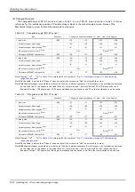
(2) Changeable
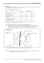
The changeable angle of RV-13F series is shown in
. Use as reference for the installation position of
Mechanical Stopper screw and the parameter setup value.
Table 3-5 : Changeable angle (RV-13F series)
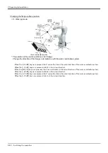
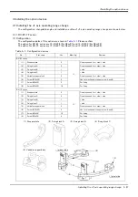
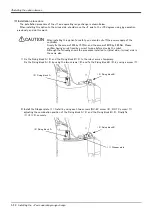
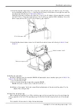
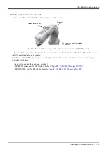
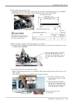
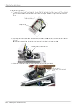
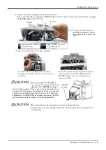
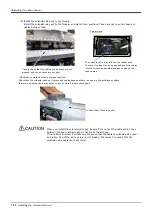
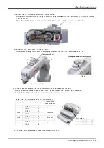
The installation procedure of the J1 axis operating range change is shown below.
[Note] When installing this option for safety, you should cut off the power supply of the controller.
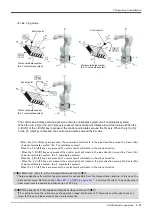
Surely fix the screw of M4 by 15.7Nm, and the screw of M10 by 26.5Nm, and the screw of M12 by
26.5Nm. Please confirm having surely fixed by correct torque before moving the robot.
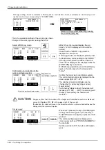
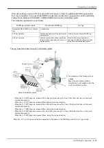
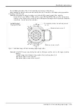
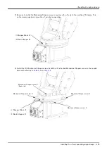
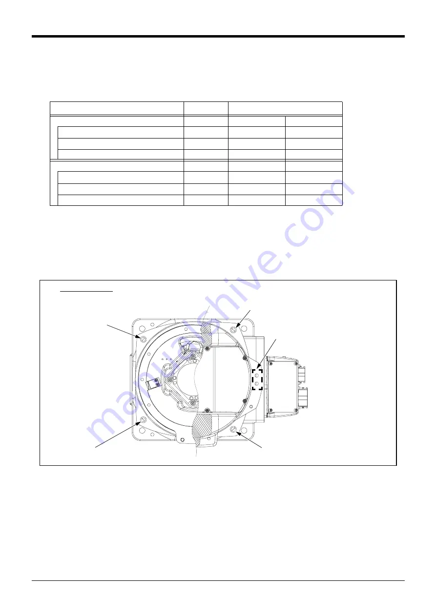
Fig.3-2 : Installation image of J1axis operating range change option (RV-13F series)
[Example] In the RV-13F series, when li side to +32.5 degree and - side to -122.5 degree, install the
Mechanical Stopper screw in the position of (A) and (C).
Item
Standard
Changeable angle
+ (plus) side
+190
+30
+120
Mechanical Stopper screw position
Note1)
Note1)Symbol: “(A)” - “(D)” in the
"Fig. 3-2: Installation image of
J1axis operating range change option (RV-13F series)"
-
(A)
(B)
Mechanical Stopper position
+193
+32.5
+122.5
Parameter (MEJAR) setting value
+190
+30
+120
+ (minus) side
-190
-30
-120
Mechanical Stopper screw position
-
(D)
(C)
Mechanical Stopper position
-193
-32.5
-122.5
Parameter (MEJAR) setting value
-190
-30
-120
The installation position of Stopper
Block J1
(Back side)
Mechanical Stopper screw A
Mechanical Stopper
screw B
Mechanical Stopper screw D
Installation image
(Top-view of J1 axis)
Mechanical Stopper screw C

