3Installing the option devices
Installing the hand output cable 3-71
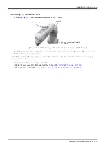
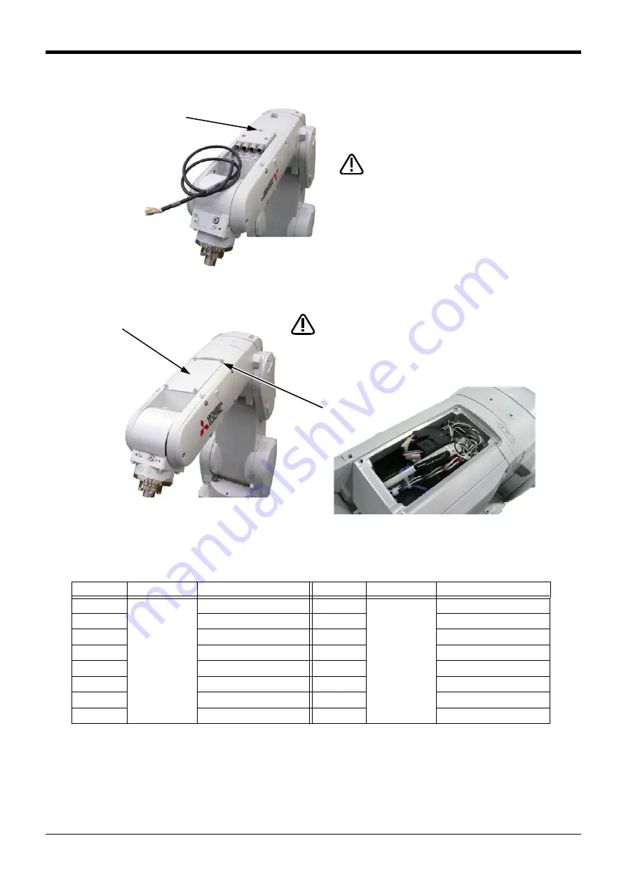
6) Fixes the cable clamp box securely by the fixing screws as before. Installs carefully so that the cable may not
be inserted.
7) Fixes the No.2 arm cover U securely by the fixing screws as before. Installs carefully so that the cable may
not be inserted.
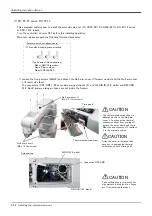
This completes installing the cable clamp box. Pin assign of the hand output cable is shown in
.
Table 3-9 : Pin assign of hand output cable
Color
Connector
Pin number: names
Color
Connector
Pin number: names
Yellow
GR1
A1: +24V
Green
GR2
A1: +24V
-
A2: Reserved
-
A2: Reserved
Purple
A3: GR1 (Hand output 1)
Red
A3: GR5 (Hand output 5)
Brown
A4: GR2 (Hand output 2)
White
A4: GR6 (Hand output 6)
Blue
B1: GR3 (Hand output 3)
Gray
B1: GR7 (Hand output 7)
Black
B2: GR4 (Hand output 4)
Pink
B2: GR8 (Hand output 8)
-
B3: Reserved
-
B3: Reserved
-
B4: Reserved
-
B4: Reserved
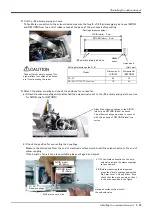
When you install the
cable clamp box, be
careful to not put the
cable between the cable
clamp box and arm. If the
cable is inserted, it will
become the cause that
the cable be broken.
CAUTION
Fixing screws
(Three places)
* The figure is the example to which the J4 axis was
moved to upside down position by jog operation.
Four fixing screws
No.2 arm cover U
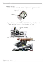
The condition of storing the cable inside the No.2 arm cover U
When you install the No.2 arm cover
U, be careful to not put the cable
between the cable clamp box and
arm. If the cable is inserted, it will
become the cause that the cable be
broken.
CAUTION

