3-74
Installing the Forearm external wiring set/ Base external wiring set
3Installing the option devices
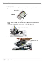
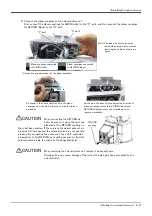
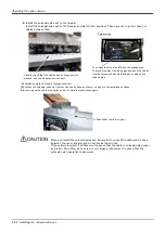
4) Install Base external wiring set on the position where CONBOX cover R was being installed, by using original
three fixing screws. Installs carefully so that the cable etc may not be inserted.
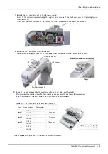
5) Connects the cable of Base external wiring set to the force sensor interface etc which customer will use. The
Outlet and cable names of each cables are shown in
.
Table 3-12 : Cable to pull out and outlet
6) The cable which connects the force sensor interface needs grounding.
The method is shown below.
This completes installing the Base external wiring set.
Base external wiring set
Cable to pull out
Robot side connection
connector
Grounding process
Outlet
Name
Purpose of use
1F-HA01S-02
(For SExx01)
1F-HA01S-01
(For SExx02)
<1>
E ・ F1
Force sensor interface
CNOP1
Require
<2>
Reserved
<3>
LAN
Vision sensor controller
LAN
Not require
<4>
RIO
Reserved
CNOP1
Require
1F-HA02S-02
(For SExx01)
1F-HA02S-01
(For SExx02)
<1>
E ・ F2
Force sensor interface
CNOP1
Not require
<2>
E ・ F1
Reserved
CNOP1
Require
<3>
LAN
Vision sensor controller
LAN
Not require
<4>
RIO
Reserved
CNOP1
Require
Base external wiring set
(1F-HA01S-01, 1F-HA02S-01,
1F-HA01S-02, 1F-HA02S-02)
Grounding
Connector
*1)
*1) Grounding process
Skins the sheath and grounds the metal braid section to the grounding terminal of customer preparation.
Note) Don't damage the shield line
Metal braid section
Sheath
Sheath
20 ~ 30mm
Communication cable
Grounding cable clamp
(customer preparation)
Recommendation
Type: AL3
Maker: K.C.C. SHOKAI
LIMITED
<Base external wiring set. Process of the communication cable>
Grounding
*1)


