background image

– 18 –

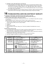
d.  Outdoor type motor

(a)  Before reassembling, apply a sealing agent (ThreeBond 1102D or the like) to the frame fitting surface of the 

bracket.

(b)  When the flinger, water flinger and V-ring will be fitted to the shaft through hole, apply a thin layer of 

grease (Alvania S2 or the like) to the bracket surface. Take care not to stain the shaft with grease or oil. 
The mounting dimensions of the flinger and water flinger shall be identical with those before disassembly. 
(Normally, the gap between the flinger and bracket shall be 0.3 to 0.5mm, and that between the water flinger 
and bracket shall be 1 to 1.5mm.) Bring the V-ring into slight contact with the bracket. After fitting them, turn 
the shaft by hand, and check for abnormal noise and non-smooth rotation.

e.  When open bearings are used 

When installing the housing cover and bracket, check the grease port in the housing cover and the oil supply 
and drain ports in the bracket, and ensure that they are located in the same positions as before disassembly.

f.  Totally-enclosed fan-cooled motor 

When installing the fan, apply grease (Alvania S2 or the like) to the shaft mounting surface. (So, the fan can be 
removed easily next time.) Apply a screw locking agent (ThreeBond 1401B or the like) to the setscrews of the fan 
before tightening.

g.  Tightening of screws 

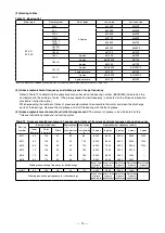
Tighten the screws to the tightening torques shown in Table 15. To install the frame bracket of motor of frame 
size 132 or below, fit the clamping bolts (through bolts) perpendicularly to the fitting surface. 

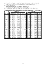
Table 15  Screw tightening torque standard (iron) 

Screw size

M4

M5

M6

M8

M10

M12

M16

Torque (N·m)

1.65

3.2

5.5

13.2

26.5

46

110

(Note) Except tapping screws 

(2) Installation of bearings

When assembling the bearings onto the shaft, clean the fitting section of the bearings, remove any scratches and 
protrusions, and hen fit with the following method. 
a.  Installation of a shielded ball bearing

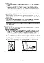
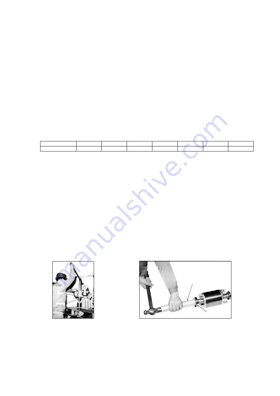
(a)  Apply oil on the bore diameter of the bearing and the fitting face of the shaft, and press the bearing squarely 

onto the shaft by placing a suitable piece of pipe against the inner ring and carefully pressing with a press 
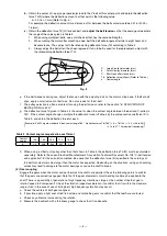
as shown in Fig. 11. If a press is not available, tap the bearing lightly and slowly lower it as shown in Fig. 12. 
In this case, 

take not to pry the bearing or to contact the pipe against the bearing retainer seal or outer 

ring section.

(b)  When heating the bearing with a heater or oven before insertion, heat the bearing to approx. 90°C (

take care 

not to exceed 100°C), and then fit it onto the shaft. When mounting onto the shaft, always wear protective 
equipment to prevent burns, etc.

(c)  After fitting the bearing onto the shaft, check visually and with a thickness gauge that there is no gap between 

the shaft and bearing.

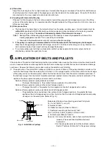
(d)  If the lock nut is tightened or the bearing is mounted on the bracket before the bearing cools down, the 

bearing may be wrenched. Reassemble after the bearing sufficiently cools down.

Pipe

Bearing

(Nagoya Works B750058-1)

Fig. 12  Installation of the bearing with a hammer

Pipe

Bearing

(Nagoya Works B750058-3)

Fig. 11  Installation of the bearing with a press

Summary of Contents for SF-PR Series

Page 1: ...Notice Make sure that this Instruction Manual is delivered to the end user of this motor BAN S 15917 A 3 PHASE SQUIRREL CAGE INDUCTION MOTOR MODEL SF PR SERIES INSTRUCTION MANUAL ...

Page 2: ......

Page 3: ...tion Failure to observe this could lead to electric shocks injuries or fires etc as well as motor damage or failure Refer to page 7 Piping and wiring Always follow the connection drawing in the terminal box or the Instruction Manual when connecting the power cable Failure to do so could lead to electric shocks or fires Refer to page 8 Do not bend pull or catch the power cable or motor lead wires w...

Page 4: ...the shaft end Failure to do so could lead to injuries Refer to page 9 Confirm the rotation direction before coupling the motor with machine Failure to do so could lead to machine damage Refer to page 9 Never get on or hang from the motor Failure to observe this could lead to motor damage or injuries Refer to page 2 Do not touch the motor shaft end keyway with bare hands Failure to observe this cou...

Page 5: ...AR OPERATION 9 10 VIBRATION 10 11 MAINTENANCE 11 12 SERVICING OF COILS AND INSULATION 12 13 MAINTENANCE OF BEARING AND LUBRICATION 12 14 DISASSEMBLY OF MOTOR AND REMOVAL OF BEARINGS 17 15 REASSEMBLY OF MOTOR AND INSTALLATION OF BEARINGS 17 16 TROUBLESHOOTING SERVICING AND PRODUCT WARRANTY 19 17 MOTOR CONSTRUCTION DRAWINGS 21 18 DISPOSAL 24 19 EXPORTING 24 20 COMBINATION WITH THE INVERTER 25 21 CHE...

Page 6: ......

Page 7: ...een set on the partner machine will be very hazardous 2 Storage a Observe the following points when the motor is not to be used immediately after delivery a Store the motor in a clean and dry place b When storing the motor outdoors or where it will be subject to humidity cover the entire product with a waterproof cover to protect it from rain water and dust b Observe the following points when stor...

Page 8: ...e motor in a high humidity high dust high temperature place where water or oil may come in contact Select a well ventilated clean dry environment g Note that if the motor is used in a dusty area the heat radiation effect cooling effect of the motor may be degraded resulting in rise of motor temperature or dust may enter the bearings thereby causing abnormal noise and damage h If the motor is insta...

Page 9: ... Make sure that the lower side of the belt is the tensed side For this first determine the rotation direction of the partner machine and then determine the motor position Refer to Fig 3 c Refer to Table 2 for the motor and partner machine shaft to shaft distance d Belt tensioning method If the belt is too tense the bearings may be damaged or the shaft may break If the belt is too loose slipping ma...

Page 10: ...d V belt contact angle 180 Deflection force Td 180 K Td 140 0 9 46 to 53 41 4 to 47 7 for new belt tensioning Table 3 Contact angle compensation coefficient Contact angle φ 140 150 160 170 180 K 1 0 0 98 0 94 0 91 0 9 h When using a V belt or V pulley other than that shown in Table 4 the deflection force Td N must be calculated separately Refer to the Japan Electrical Manufacturers Association Tec...

Page 11: ... machine with a belt an excessive force could be applied on the shaft end and bearings and the life may be shortened and damage could occur Observe the following points when making the selection and installing 1 The application of the motor side V pulley and V belt is as shown in Table 4 If the pulley diameter is smaller or the number of belts larger than the values given in Table 4 or if the step...

Page 12: ...5 150 160 170 200 224 224 224 265 265 20 35 35 50 63 63 82 101 101 101 136 161 5 161 5 187 11 to 13 11 to 12 14 to 16 14 to 16 19 to 22 22 to 25 23 to 25 24 to 26 25 to 28 27 to 31 39 to 45 40 to 46 44 to 51 46 to 53 8 8 to 11 7 8 to 11 11 to 14 11 to 14 15 to 19 17 to 22 18 to 23 18 to 24 20 to 25 22 to 27 30 to 39 31 to 40 34 to 44 36 to 46 3V 3V 3V 3V 3V 3V 3V 3V 3V 3V 5V 5V 5V 5V 1 2 2 2 3 3 4...

Page 13: ...reaker commensurate with the rated output of that particular motor There are three classes of general motor insulation Class E Class B and Class F If high temperature insulation material such as Class F insulation is used the temperature in the terminal box will be relatively high Thus use wiring cables and insulation tape that have a high temperature resistance Refer to Table 6 Table 6 Examples o...

Page 14: ...ng Power supply R S T U1 V1 W1 V2 W2 U2 Starter Starter U1 V1 W1 U1 V1 W1 V2 W2 U2 U2 W2 V2 Y starting V1 U1 W1 6 terminals W2 U2 V2 Full voltage starting Case 400V Case 200V Power supply R S T U1 V1 W1 U5 V5 W5 V2 W2 U2 V6 W6 U6 Power supply R S T U1 V1 W1 U5 V5 W5 V2 W2 U2 V6 W6 U6 Case 400V Starter U1 V1 W1 U1 V1 W1 U5 V5 W5 V2 W2 U2 V6 W6 U6 U1 V1 W1 U1 V1 W1 U5 V5 W5 V2 W2 U2 V6 W6 U6 Y start...

Page 15: ...reversed In this case remove the key installed on the shaft If the rotation direction must be changed interchange two of the three power wires connected Note that the rotation direction is fixed if a skew fan is used Be sure to refer to the outline dimension drawings for more details g Is the connection with the machine correct Refer to Section 5 COUPLING WITH MACHINE h When using a star delta Y Δ...

Page 16: ...lue in is for reference c If the machine side unbalance is large due to the installation of a fan or blower etc directly onto the motor shaft or direct coupling with the partner machine the motor vibration will increase and may damage the bearings etc The motor side balance must be within G2 5 specified in JIS B 0905 balance of rotation devices d If the motor vibration is significant check the res...

Page 17: ... amount of separated oil may leak at the initial stage but this will not affect the operation Touching any part of the bearings or frame to check the temperature is dangerous Use a temperature measuring device such as an alcohol thermometer 3 Monthly inspections a Deterioration or consumption of grease Replenish or replace the grease according to the maintenance schedule Refer to 13 4 5 b Check th...

Page 18: ...operation state and ambient atmosphere dust and moisture The consumption of grease used to lubricate the bearings is very low but special care must be taken to the lubrication to prevent remarkable wear or accidents 1 Bearing lubrication and maintenance procedures Table 10 Bearing lubrication and maintenance procedures Shielded ball bearings Ball bearings roller bearings Motor application range Ac...

Page 19: ...his particular arrow is always directed towards the shaft For a horizontal structured motor the grease removal device is located below the shaft Thus the arrow must be directed upwards towards the shaft Refer to Fig 7 b If the grease removal device is installed with a screw be sure to install it with the screw in the same manner and condition as it was installed before d Do not charge the grease m...

Page 20: ... with the fresh grease 5 Grease replenishment amount and initial charge amount The amount of grease is also indicated on the Grease lubrication procedure instruction plate Table 12 Grease replenishment amount grease replenishment frequency and whole grease change frequency Bearing number Bearing dimensions Replenishment amount while in usual operation g Initial charge amount during disassembling g...

Page 21: ...th a good lubrication performance Replenish the grease Roller dropping noise This noise is generated due to the radial clearance and the relation of the clearance between the retainer and rolling element If the bearing is being used in a horizontal rotor this noise is generated when the balls drop faster than the retainer due to the gravity of the rolling element when in a no load area near the to...

Page 22: ...meter mm Clearance C2 Normal CM C3 C4 More than Less than Min Max Min Max Min Max Min Max Min Max 10 18 24 30 40 50 65 18 24 30 40 50 65 80 9 10 11 11 11 15 15 3 5 5 6 6 8 10 18 20 20 20 23 28 30 4 5 5 9 9 12 12 11 12 12 17 17 22 22 11 13 13 15 18 23 25 25 28 28 33 36 43 51 18 20 23 28 30 38 46 33 36 41 46 51 61 71 Remarks When using the clearance as the measurement clearance the clearance compens...

Page 23: ...ig 9 set the claws on the bearing inner ring and turn the handle to draw it out For the motor that requires grease lubrication set the claws of the tool on the housing cover as shown in Fig 10 and draw out the bearing Check for difference in length between the right and left parts of the tool If the bearing is drawn out in an inclined state the shaft fitting surface may be deformed 15 REASSEMBLY O...

Page 24: ...mping bolts through bolts perpendicularly to the fitting surface Table 15 Screw tightening torque standard iron Screw size M4 M5 M6 M8 M10 M12 M16 Torque N m 1 65 3 2 5 5 13 2 26 5 46 110 Note Except tapping screws 2 Installation of bearings When assembling the bearings onto the shaft clean the fitting section of the bearings remove any scratches and protrusions and hen fit with the following meth...

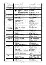
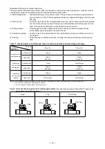
Page 25: ...e of shipment whichever is shortest b This warranty covers the shipped product only Responsibility for customer losses or compensation attributed to breakdown of this product are not covered by the warranty c For important machines prepare spare machines or motors or ensure the redundancy d The product modified or repaired by the customer is not covered by the warranty Table 16 Troubleshooting and...

Page 26: ...ect 2 The switch contact is faulty 1 Reselect the switch 2 Adjust the switch 4 The motor overheats 1 The stator winding is faulty 2 Overload 3 The power is faulty 4 The usage conditions are incorrect 1 Have specialist repair 2 Reselect the motor rating 3 Improve the power facility 4 Review the usage conditions 5 The speed drops The speed does not increase The acceleration is slow The motor does no...

Page 27: ...stallation leg 8 Preloaded spring SF PR 100L to 132M SF PRV 100L to 132M A 8 7 6 5 4 3 2 1 F E 7 8 D C 9 B G A 0 8 7 6 5 4 3 2 1 F E 7 8 D C 9 B 2 1 Frame 10 Shaft end key 1 Frame 10 Shaft end key 2 Eye bolt 11 Shaft 2 Eye bolt 11 Shaft 3 Stator core 12 Terminal box 3 Stator core 12 Terminal box 4 Rotor core 13 External fan 4 Rotor core 13 External fan 5 Stator coil 14 External fan cover 5 Stator ...

Page 28: ...ion leg 8 Bearing SF PR 180LD to 225S SF PRV 180LD to 225S A 0 8 7 6 5 4 3 2 1 E B 7 D C 8 9 F A 0 8 7 6 5 4 3 2 2 1 E B 7 D C 8 9 1 Frame 9 Preloaded spring 1 Frame 9 Preloaded spring 2 Eye bolt 10 Shaft end key 2 Eye bolt 10 Shaft end key 3 Stator core 11 Shaft 3 Stator core 11 Shaft 4 Rotor core 12 Terminal box 4 Rotor core 12 Terminal box 5 Stator coil 13 External fan 5 Stator coil 13 External...

Page 29: ...drawing Take care that the drain hole is not clogged 5 Painting Paints excelling in weather resistance salt water resistance and chemical resistance are used Table 17 Standard parts of shaft through holes of outdoor type motors horizontal type with legs Frame No Installation method part 80 to 132 160 to 225 Installation with shaft horizontal Anti load side Flinger Flinger Load side Flinger End cov...

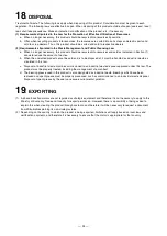
Page 30: ...nd is to be disposed of it must be handled as industrial waste as stipulated in this law c Disposal of industrial waste must be commissioned to an industrial waste disposer approved under this law The product must be properly treated including the management of a manifest d The bearing grease used in this product is also designated as industrial waste Bearings which have been replaced and spent gr...

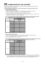
Page 31: ... 0 2 2 2 5 3 7 2 5 5 5 2 0 7 5 2 0 11 1 5 15 1 5 18 5 1 5 22 1 5 30 1 0 37 1 0 45 1 0 55 0 7 Where using a 700 series inverter a Set Pr 14 the selection of applied load to 0 factory setting For constant torque load setting b Set Pr 71 the applicable motor to 1 constant torque motor setting c Set a value from Table 19 to Pr 0 torque boost Table 19 Table of setting values Common to 200VAC and 400VAC...

Page 32: ...5 2 0 2 0 2 4 55 2 0 2 0 Where using a 700 series inverter a Set Pr 14 the selection of applied load to 0 factory setting For constant torque load setting b Set Pr 71 the applicable motor to 1 constant torque motor setting c Set a value from Table 19 to Pr 0 torque boost Table 21 Table of setting values Common to 200VAC and 400VAC classes where generating the output of 6Hz 150 torque maximum torqu...

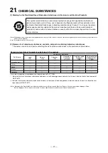
Page 33: ...dous substances contents and parts containing hazardous substances The names contents and parts containing the six hazardous substances in this product are listed below Names and contents of hazardous substances in the product Part Name Hazardous Substances Lead Pb Mercury Hg Cadmium Cd Hexavalent Chromium Cr VI Polybrominated biphenyls PBB Polybrominated diphenyl ethers PBDE Structure part Stator...

Page 34: ...用等要遵守各自治体的法律法规的要求 Note This symbol mark is for China only 2 含有有害6物质的名称 含有量 含有部品 本产品中所含有的有害6物质的名称 含有量 含有部品如下表所示 产品中有害物质的名称及含量 部件名称 有害物质 铅 Pb 汞 Hg 镉 Cd 六价铬 Cr VI 多溴联苯 PBB 多溴二苯醚 PBDE 构造部件 转子 定子 制动器 检测器 本表格依据SJ T11364的规定编制 表示该有害物质在该部件所有均质材料中的含量均在GB T 26572规定的限量要求以下 表示该有害物质至少在该部件的某一均质材料中的含量超出GB T26572规定的限量要求 注 并不保证发往中国的产品带有 电器电子产品有害物质限制使用标识 将产品发往中国之前 请确认是否符合产品的高效规定和安全标准等 ...

Page 35: ......

Page 36: ...IB NA 0100014ENG A 1611 IP Printed Japan New publication effective Nov 2016 Specifications subject to change without notice Printed in Japan on recycled paper ...

Reviews: