background image

Mounting on User’s Equipment

Troubleshooting

14

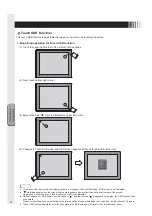
7. Mounting on User’s Equipment

 Notes on Installation

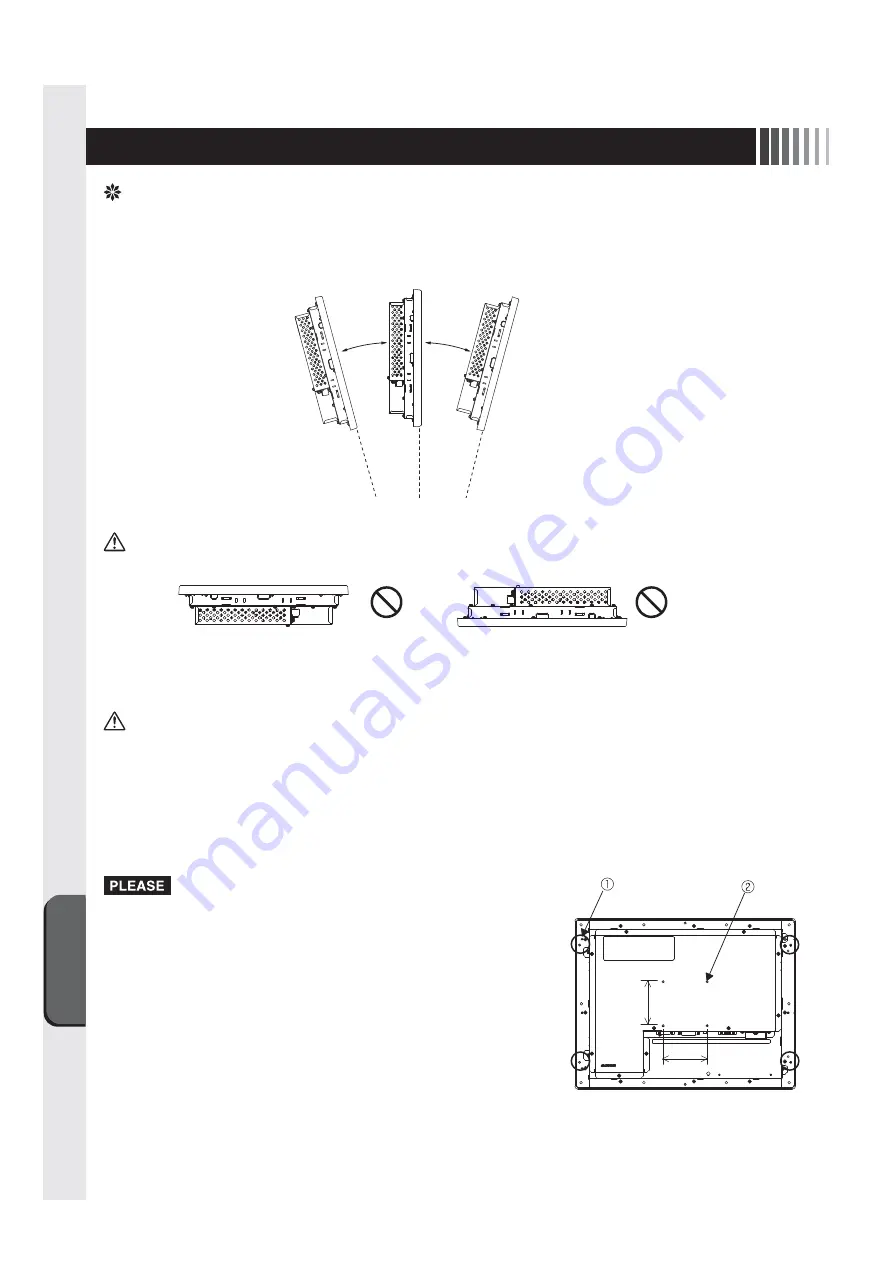
1. Mounting angle 

This unit is mounted vertically in principle.
When mounting the unit on the skew, an angle must be 15 degrees or less.

CAUTION

 Do not use this unit upward or downward.

2. Mounting screws

Use M4 screws to mount the unit onto a user’s cabinet or a VESA arm.

CAUTION

 Use of nonconforming screws may cause injury or a failure.

  Tighten all screws securely to avoid loosening. (However, over-tightening may damage a screw. An appropriate torque 

is 98 to 137 N•cm.)

  Give the touch panel monitor side tightening depth of the mounting screws as follows:
  (1) Holes for mounting on user’s equipment (4 holes): 10 mm at maximum
  (2) Holes for mounting on VESA arm (4 holes): 6 mm at maximum (Mounting pitch: 75 mm)

 Mount the unit on user’s own risk. Note that the manufacturer is not 

responsible for an accident in installation.

 If the touch panel monitor cannot be mounted by laying it down, it takes 

two or more people to mount the unit. Falling the unit may cause injury.

 Before mounting a VESA arm, be sure to read instructions of the arm 

carefully.

15° or less

15° or less

4holes

4holes

75mm

75mm

Summary of Contents for TSD-AT1519-MN

Page 1: ...5 5 5 4 接続 電源の接続 ケーブルの接続 5 画面調節 画面の調節 タッチOSD機能 6 6 6 7 7 8 7 お客様筐体への取付け 取付上のご注意 8 困ったとき 故障かな と思ったら お手入れ 14 14 15 15 17 9 付録 仕様 さくいん 17 18 19 接 続 画 面 調 節 6 機能 自動画面表示 パワーマネージメント機能 タッチドライバのインストール 12 12 12 13 もくじ ページ アナログ抵抗膜方式 アナログ抵抗膜方式 困 っ た と き お 客 様 筐 体 へ の 取 付 け インターネットホームページ http www mee co jp sales visual touch monitor 製品情報などを提供しています 取扱説明書 15型タッチパネルモニター TSD AT1519 MN 形名 ...

Page 2: ...この装置は クラスB機器です この装置は 住宅環境で使用することを目的としていますが この装置がラジオやテレビジョン受信機に 近接して使用されると 受信障害を引き起こすことがあります 取扱説明書に従って正しい取り扱いをしてください 本機は付属の信号ケーブル 当社推奨の電源セッ トおよび当社推奨のケーブルを使用した状態でVCCI基準に適合しています 本書の内容の一部または全部を無断で転載することは固くお断り します 本書の内容について 将来予告なしに変更することがあります 本書の内容については 万全を期して作成しましたが 万一誤り 記載もれなどお気付きの点がありましたらご連絡ください この取扱説明書に使用している表示と意味は次のようになっています 誤った取扱いをしたときに生じる危険とその程度を 次の表示で区分して説明しています 図記号の意味は次のとおりです Windows Vista Win...

Page 3: ...きは 電源プラグをすぐ抜く 使用禁止 警告 禁止 禁止 けが 火災 感電の原因 になります 修理 改造をしない 特にお子さまにご注意 本体包装のポリ袋を頭からかぶると窒息の 原因になります ポリ袋で遊ばない 禁止 修理 改造禁止 プラ グ を抜く 水ぬれ禁止 風呂場や水のかかるところに置かない 液晶を口にしない 水などがタッチモニタの内部に入った場合はすぐに本 体の電源を切り DC入力電源を切ってお買い上げの 販売店にご連絡ください そのまま使用すると 故障 火災 感電などの原因になります 液晶パネルが破損し 液晶が漏れ出た場合は 液晶を吸い 込んだり 飲んだり しないようにしてください 中毒を起こ す恐れがあります 万一口に入ってしまったり 目に入って しまった場合は 水でゆすいでいただき 医師の診断を受 けてください 手や衣類に付いてしまった場合は アルコ ールなどで拭き取り 水洗いし...

Page 4: ...たこの製品に関する技術相談 アフターサービス等も日本国外 ではおこなっていません This Touch monitor is designed for use in Japan and can not be used in any other countries 画面の位置は 目の高さよりやや低く 目から約40 70cmはな れたぐらいが見やすくて目の疲れが少なくなります 明るすぎる部屋は目が疲れます 適度な明るさの中でご使用くだ さい また 連続して長い時間 画面を見ていると目が疲れます 上手な見方 タッチパネルモニターのお手入れ タッチパネルモニターの上手な使い方 国内専用 タッチパネルモニターの表面にほこりや汚れがついているときは 柔ら かい布でやさしく拭いてください 表面は傷つきやすいので硬いもの でこすったり 叩いたり しないでください また 液晶パネルは壊れやす いので強く押し...

Page 5: ... Sub 9ピン フェライトコアなし タッチ通信ケーブル USB タイプA タイプB お客さま相談窓口のご案内 ケーブルクランパ 1個 クランパ固定ネジ 1個 お客さま相談窓口のご案内 安全に関する注意書き 安全に関する注意書き 映像信号 入力コネクタ DVI D 24ピン DVI Dケーブルを 接続します DVI Dケーブルは 付属されていません 映像信号 入力コネクタ ミニD Sub15ピン 映像信号ケーブル ミニD Sub 15ピン を接続します タッチ通信コネクタ USB タイプB タッチ通信ケーブル USB を接続します タッチ通信コネクタ D Sub 9ピン タッチ通信ケーブル D Sub 9ピン を接続します 電源入力コネクタ 端子台 電源コードを接続します 映像信号入力コネクタ DVI 24ピン とタッチ通信コネクタ USDタイプB の間のコネクタは使用することが できませ...

Page 6: ... 24V 接地 GND 24V 2 N G 絶縁板 DC24 供給電源 ケーブルの接続 ケーブルは 接続後必ずそれぞれの固定ネジで確実に固定してください ケーブルを接続する前に 本機 コンピュータおよび周辺機器の電源を切ってください USBの接続は USBハブなどを介さず 直接コンピュータに接続することをおすすめします RS 232C シリアルポート DVI出力 VGA出力 1 3 4 USB DVI D 2 コンピュータ ミニD Sub 15ピン USB タイプB D Sub 9ピン DVI 入力 USB USBポート 1 映像信号ケーブル ミニD Sub 15ピン 4 タッチ通信ケーブル D Sub 9ピン 3 タッチ通信ケーブル USB 2 映像信号ケーブル DVI D VGA 入力 タッチ通信ケーブルは 3または4どちらかのみ を接続します RS232C 映像信号ケーブルは 1また...

Page 7: ...tup を選択することにより 自動画面調節を開始します 入力された信号を検 出し Clock Phase H Position V Position の自動調節と 入力信号に適した色合いへ自動調 節を開始します 自動調節完了後は 調節に問題ないかを確認する以下の OSD が表示されます 問題ない場合は Yes を選択してください 問題がある場合は No を選択し 手動で調節をしてください DOS プロンプトのように文字表示のみの場合や画面いっぱいに画像が表示されていない場合 単色の画像の場 合は自動画面調節がうまく機能しない場合があります コンピュータやビデオカードによっては 自動画面調節がうまく機能しない場合があります この場合 マニュア ル画面調節でお好みの画面に調節してください 画面の調節 2 マニュアル調節 1 本機およびコンピュータの電源を入れてください 2 次項の タッチ OS...

Page 8: ...タッチOSDモードに入ります の手順通りにタッチされていない場合 タッチOSDモードへ移行できません OSD画面は表示されません にて画面左下以外の場所をタッチされると 画面左上の 表示は消えます この状態で を実施してもOSD画面は表示されません OSD画面が表示されない が表示されない が途中で消える場合は タッチOSD機能は動作していません 上記以外の場所を一度タッチして タッチ位置にマウスカーソルが追従していることを確認し 再度 の手順を 行なってください OSD画面は タッチOSD機能設定 P10 OSDの表示 機能により表示することも可能です 1 タッチ OSD 機能動作モードへの移行方法 タッチ OSD 機能 ...

Page 9: ...領域に 分けてキーを配置しています 下図に示すキー領域をタッチすることで Menu Select ボタンと同じ動作ができます Menu Select 画面位置 キー名 動作 左下 右下 右上 左上 Menu Select OSD画面が表示されている状態で Exit 選択に移動します また OSD機能の操作最中には1つ上の画面に戻ります 選んだ調節項目を決定します 調節項目 グループへ移動します 選んだ調節項目の値を調節 増 します 調節項目 グループへ移動します 選んだ調節項目の値を調節 減 します 注 タッチOSD機能動作モード中は通常のタッチ動作は停止します 2 タッチ OSD 機能動作モード解除方法 3 タッチ OSD 機能操作方法 ...

Page 10: ... 右下 D 左下 です タッチドライバのUPDDインストールの タッチOSD をクリックすると下図ウインドウが表示されます 右側モニタイメージ図内のA B C Dの文字部分をタッチし シーケンスを変更してください 下図参照 その後 設定保存 ボタンを押すことによって タッチシーケンスをタッチパネルモニターへ保存し ます 2 タッチOSD機能の有効 無効 タッチOSD機能の有効 無効を設定できます デフォルトは有効 チェックマーク有 です 3 OSDの表示 OSDの表示 をクリックするとOSD画面が表示されます ミニ解説 タッチシーケンス あらかじめ定められたタッチ操作の順序のことです 3 項の機能によりOSD画面を表示することも可能です 4 タッチ OSD 機能設定 ...

Page 11: ...入力時は無効 Color Mode Exit このグループの調節を終了します Cool 色温度を Cool に設定します 9300K Gain R 90 G 83 B 100 固定 Neutral 色温度を Neutral に設定します 6500K Gain R 100 G 88 B 79 固定 Warm 色温度を Warm に設定します 5400K Gain R 100 G 83 B 68 固定 User 初期設定 色温度を User に設定します USER Gain R 100 G 100 B 100 変更可 Clock Phase アナログ接続の 場合のみ Exit このグループの調節を終了します Clock 左右の画面サイズを調節します Phase 画像のにじみ ノイズ クロック位相 を調節します Management Exit このグループの調節を終了します OSD Displa...

Page 12: ...A 75Hz 800 x 600 37 9kHz 60Hz 正 正 SVGA 60Hz 800 x 600 48 1kHz 72Hz 正 正 SVGA 72Hz 800 x 600 46 9kHz 75Hz 正 正 SVGA 75Hz 1024 x 768 48 4kHz 60Hz 負 負 XGA 60Hz 1024 x 768 56 5kHz 70Hz 負 負 XGA 70Hz 1024 x 768 60 0kHz 75Hz 正 正 XGA 75Hz 本機は下表に示す種類のタイミングの自動判別をおこない画面情報を設定しますので コンピュータに接続すると 自動的に適切な画面を表示します ただし コンピュータによっては画面にちらつきやにじみが生じることがあります また 入力信号によっては うまく表示できないこともあります その場合は画面調節 P7 をおこなってく ださい 工場プリセットタイミ...

Page 13: ...ァイルですので ご使用のコンピュータにファイルを一旦保存し 解凍ください setup exe をダブルクリックし 実行ください インス トールする場合は 管理ユーザー Administrator でログインしてください 4 5 5 4 4 4 右記のようなウィン ドウが表示されますので 実行 を クリ ックください USB接続の場合 Controller USB USB を選択し インス トール を クリ ックください ドライバファイルのインス トールを開始します インス トール完了です 閉じる をクリ ックしてください タッチ ドライバをインス トールする前に必ず ユーザーズガイ ド をお読みください インス トール直後 ドライバが正常に動作しない場合は コンピュータを再起動してください シリアル接続の場合 Controller Serial Serial を選択し Serial Por...

Page 14: ... 取付けはお客様の責任においておこなってください 万一事故が発生した場合でも 当社はその責を負いかねますので ご了承ください タッチパネルモニターを倒したまま固定できないときは 2人以上で 取付け作業をおこなってください 落下してけがの原因となります VESA規格アームの取付け作業をおこなう前に アームの取扱説明 書を必ず読んでください ネジゆるみ防止のためすべてのネジをしっかりと締めてください ただし 締め付けすぎるとネジがこわれることが あります 98 137N cmが適切な締め付け トルクです 取付ネジのタッチパネルモニター側への入り込み深さは次のとおりとしてください お客様筺体取付穴 4箇所 MAX10mm VESA規格アーム取付穴 4箇所 MAX6mm 取付ピッチ 75mm 指定以外のネジを使用した場合はケガや故障の原因になります 4箇所 75mm 75mm 4箇所 ...

Page 15: ...ェックしてください 1 DC 電源コードを正しく接続してください 2 正常に電気が供給されているか 別の機器で確認してください 3 OSD 画面で Contrast および Brightness を調節してください OSD 画面が表示されれば本機は正常です P11 4 コンピュータとの接続を確認してください 5 パワーマネージメント機能が作動していると画面が表示されません タッチ操作またはキーボードの適当なキーを押すかマウスを動かしてく ださい P12 6 映像信号ケーブルを正しく接続してください 7 コンピュータの電源が 切 になっていないか確認してください 画面に何も映らない 1 分配器を使用している場合は コンピュータに直接入力してください 2 OSD メニュー Clock Phase の Phase を選択し調節ください 3 上下にちらつく場合は コンピュータのリフレッシュレートを...

Page 16: ...nt の Recall で工場出荷設定に戻してください このようなときは チェックしてください 数秒間画面が不安定になる 表示状態がおかしい 1 ご使用のコンピュータによっては 入力信号を切り替えると画面が数秒 間不安定になることがありますが 故障ではありません 1 タッチドライバのユーザーズガイドに従ってタッチドライバが正し くインストールされていることを確認してください 2 タッチ通信ケーブルを確実に接続してください 3 キャリブレーションをおこなってください 詳しくはタッチドライバ 用ユーザーズガイドをご覧ください 4 パソコン システム の立ち上げ時には 周辺機器の認識をおこなって おり タッチ操作をおこなうと正常な認識ができませんので システム が完全に立ち上がったあとに操作をおこなってください 5 タッチパネルモニターに電源を入力してから約 5 秒間はタッチコン トローラがイニ...

Page 17: ...使用いただくため 定期的にタッチパネルのお手入れをおこなってください お手入れの際は電源コードを抜いてから 柔らかい布で軽くふ き取ってください 電源を入れたままお手入れをおこなうと タッチパネルが反応 し 故障の原因となります 汚れがひどいときには水に浸した布をよくしぼってふき取り 乾いた柔らかい布で仕上げてください 販売店におまかせください 定期的な掃除は火災 故障を防ぎ ます 特に梅雨期の前におこなうのが効果的です 内部掃除費用については販売店にご相談ください 定期的にお手入れを 1年に1度は内部の掃除を ...

Page 18: ... 15W VCCI クラス B UL c UL 376 W 291 H 67 D mm 約3 5kg Auto Setup Brightness Contrast H Position V Position Sharpness Color Mode Cool Neutral Warm User Clock Phase OSD H Position OSD V Position OSD Timer Source Recall この製品は一般工業等を対象とした汎用品として製作されたもので 人命にかかわるような状況下で使用される機器あるいは システムに用いられることを目的として設計 製造されたものではありません この製品を原子力用 電力用 航空宇宙用 医療用 乗用移動体用の機器あるいはシステムなど特殊用途への適用をご検討の 際には 当社の営業担当窓口までご照会ください この製品は厳重な品質管理体...

Page 19: ... 画素ピッチ 画面がちらつく 画面上に黒点 点灯しない点 や輝点 点灯したままの点 が少数ある 画面調節 画面に何も映らない 画面を切り替えても前の画面の 像が薄く残っている 輝度 機能 供給電源 ケーブルの接続 工場プリセットタイミング 故障かな と思ったら ご使用の前に 困ったとき コントラスト 18 5 18 15 15 7 11 12 15 15 18 12 6 18 6 12 15 2 15 11 18 か 安全のために必ず守ること 映像信号ケーブル 映像信号入力コネクタ お手入れ 3 5 6 15 5 4 17 あ 入力信号 7 12 16 18 な ユーザーメモリ機能 12 や パワーマネージメント機能 ビデオ信号 表示画素数 表示サイズ 表示状態がおかしい 付属品の確認 付録 本体背面 12 15 12 18 18 18 15 16 5 18 5 は マニュアル調節 7 ま...

Page 20: ...40D871150A10 http www mee co jp ...

Page 21: ...5 Display Adjustment Image Adjustment for analog connection Touch OSD Function 6 Functions Automatic Screen Display Power Management Function Software Installation for Touch driver 7 Mounting on User s Equipment Notes on Installation 8 Trouble Shooting If the Device Malfunctions Cleaning Instructions 9 Addendum Specifications 2 3 5 5 5 6 6 6 7 7 8 12 12 12 13 14 14 15 15 17 18 18 Before Using Prec...

Page 22: ... Beware of high voltage indicated on the back surface of the unit The symbols used in this User s Manual and their meanings are as following The dangers and the degree of danger possible as a result of mishandling are explained using the symbols below The meanings of the symbols used in Items that require particular attention Information you will find informative Reprinting any contents of this us...

Page 23: ...rly of children Playing with the plastic bag used to package this device can cause suffocation Keep away from water If water etc gets inside the liquid crystal display immediately shut off power to the main unit unplug the power cord from the power outlet and contact your vendor Using the display when wet may cause malfunction fire electric shock etc Do not place the monitor in the bathroom or in ...

Page 24: ...y other countries of Japan Furthermore technical consultation and after service etc for this device are not provided overseas This Touch panel monitor is designed for use in Japan and can not be used in any other countries For use in Japan only Effective viewing For the most comfortable viewing and to reduce eyestrain the screen should be positioned slightly lower than eye level and 40 70 cm away ...

Page 25: ...O SIGNAL INPUT CONNECTOR Mini D Sub 15pin TOUCH COMMUNICATION CONNECTOR D Sub 9pin POWER INPUT CONNECTOR Terminal block Connects the power cord TOUCH COMMUNICATION CONNECTOR USB type B Connects the touch communication cable USB Connects the touch communication cable D Sub 9pin Safety note Safety note The connector between Touch communication connector USB type B and Video signal input connector DV...

Page 26: ...ed with a screw from the top of the power supply connector prior to connection In the interests of safety secure the insulating plate again with the screw after connection Connect the input power cable to the terminal block on the rear side of the touch panel monitor FG GND 24V Earth GND 24V 2 N G Insulating plate 24V DC power supply 1 3 4 2 DVI D Mini D Sub 15pin USB type B D Sub 9pin RS 232C Ser...

Page 27: ...ock Phase H Position and V Position by detecting input signal After automatic screen adjustment completes OSD screen is displayed to verify that automatic screen adjustment functions properly Select YES when the automatic screen adjustment functions properly Select NO when the automatic screen adjustment may not function properly to execute manual adjustment The automatic screen adjustment may not...

Page 28: ...UN GLVDSSHDUV ZKHQ WRXFKLQJ ZKLOH WKH PDUN DSSHDUV SODFHV RWKHU WKDQ ERWWRP OHIW FRUQHU RI WKH VFUHHQ Under such a condition even if four is executed OSD is not indicated Ɣ 1HLWKHU LQGLFDWLRQ RI 26 VFUHHQ QRU LQGLFDWLRQ RI DQG WRXFK ZKHQ GLVDSSHDUV RQ WKH ZD WKH 26 IXQFWLRQ GRHV not operate 3OHDVH FRQILUP WKH PRXVH FXUVRU IROORZ WR WKH WRXFK SRVLWLRQ SODFH QRW OLVWHG DERYH RQFH DQG GR WKH SURFHGXU...

Page 29: ...touching following key area í Menu Select Position Key Action Bottom Left Bottom Right Upper Right Upper Left Menu Select í Move to Exit while OSD screen is indicated Or return to previous screen while OSD function is operating Decide adjustment groups and items Move to adjustment items or groups Or adjust increase the value of selected item select to adjustment items or groups Or adjust decrease ...

Page 30: ...he Touch OSD of UPDD install of touch driver then following window is indicated 2 Please change a sequence by touching the letter A B C D of the monitor in indicated figure 3 After that store a touch sequence to a touch monitor by pushing the save button 2 Enable Disable of Touch OSD function 3 OSD display Default is Enable checked OSD operation is available by installing optional OSD PCB though s...

Page 31: ...nal input of the resolution 1024x768 Color Mode Exit End the adjustment of this group Cool Sets color temperature to Cool 9300K Gain R 90 G 83 B 100 fixed Neutral Sets color temperature to Neutral 6500K Gain R 100 G 88 B 79 fixed Warm Sets color temperature to Warm 5400K Gain R 100 G 83 B 68 fixed User Default setting Sets color temperature to User USER Gain R 100 G 100 B 100 changeable Clock Phas...

Page 32: ...chine is compatible with horizontal frequencies of 30 0 61 0kHz and vertical frequencies of 55 0 75 4Hz However some input signals may not be able to display correctly even if they fall within this range In such cases please change the frequency or the resolution of your computer This device in not compatible with interlaced signals The screen may not appear properly for input signals that have th...

Page 33: ...s a compressed file Save the file in your computer and decompress the file Double click on setup exe to execute the file 4 5 5 4 4 4 Click the Run button The installation of software is completed Click the Close button Before you install main software please refer to the User s Guide ユーザーズガイ ド When the driver does not work just after installation normally please reboot the PC Serial connection Sel...

Page 34: ...ever over tightening may damage a screw An appropriate torque is 98 to 137 N cm Give the touch panel monitor side tightening depth of the mounting screws as follows 1 Holes for mounting on user s equipment 4 holes 10 mm at maximum 2 Holes for mounting on VESA arm 4 holes 6 mm at maximum Mounting pitch 75 mm Mount the unit on user s own risk Note that the manufacturer is not responsible for an acci...

Page 35: ...and correctly connected 7 The PC connected with the monitor should be on 1 If a distributor is used directly connect this product with your PC 2 Select Phase on Clock Phase of OSD menu 3 If the screen flickers up and down specify a refresh rate of the com puter at 60 Hz 1 Every LCD panel has such spots by nature The monitor has no prob lem 1 If a fixed pattern is displayed for a long time it may o...

Page 36: ... case your equipment has no problem 1 Check to make sure that the touch driver should be completely and cor rectly installed according to the user s guide for touch driver 2 Check to make sure the connection cable for touch sensor should be connected completely and correctly 3 The monitor may need to be calibrated Refer to the user s guide for touch driver 4 You cannot operate this system during y...

Page 37: ...ure Use a soft cloth when cleaning If the monitor is too soiled soak a cloth in mild detergent and give it a wring before cleaning Finish it with a dried soft cloth finally Avoid using any cleaning solution or glass cleaner Annual cleaning of the monitor inside is recommended Contact your supplier to have the monitor inside cleaned Periodic cleaning will prevent causing fire and any failure Before...

Page 38: ...device has been manufactured as a multi purpose product for use in general industrial applications and so on and has not been designed or manufactured for use with devices or systems that may represent a danger to human life Please contact a member of our sales staff if considering customized applications for nuclear power electrical power aerospace medical or passenger carrying movable equipment ...

Page 39: ......

Page 40: ...40D871150A10 ...

Reviews: