Page 6-5
Protection and Status Inputs
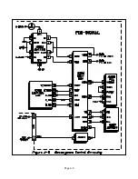
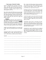
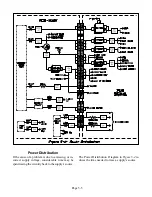
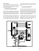
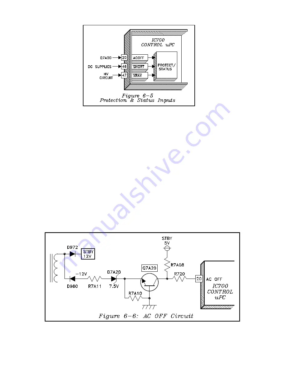
The inputs at pin 20, 46 and 47, as shown in Fig-
ure 6-5, are protection and status inputs, informing
the uPC of any abnormal operating conditions.
• AC OFF (pin 20) -- informs the uPC if
power is lost.
• SHORT (pin 46) -- informs the uPC if there
is a short on a DC supply.
• X-RAY (pin 47) -- monitors for Excess HV
and CRT Beam Current.
AC OFF Circuit
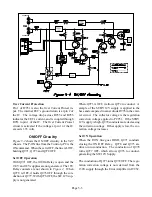
Figure 6-6 illustrates the AC OFF circuitry. With
power applied to the TV, both the STBY -12V, and
+5V Holdup supplies are present, whether the TV is
ON or OFF. The -12V supply is directed to the emit-
ter of Q7A20, through R7A11, and zener diode
D7A20. Since Q7A20 is an NPN transistor, and the
base is tied to ground, the transistor conducts.
The conduction applies negative voltage to pin 20 of
the uPC. At the same time, positive voltage from
the 5V Standby supply, through R7A08, is directed
to pin 20. The combination of the two voltages holds
pin 20 LOW. The logic at the AC OFF input of the
uPC is automatically checked every 16 msec.
If power is removed, or lost, the -12V supply drops
to zero. The 5V Holdup supply temporarily remains
at 5 volts. This drives pin 4 HIGH, informing the
uPC that power has been lost, and programmed data
is automatically stored in memory.
Summary of Contents for VS-45605
Page 11: ...Page 1 8 ...
Page 25: ...Page 3 10 ...
Page 27: ...Page 4 2 ...
Page 31: ...Page 4 6 ...
Page 33: ...Page 4 8 ...
Page 55: ...Page 8 8 ...
Page 57: ...Page 7 2 ...
Page 69: ...Page 9 2 ...


