background image

MITSUBISHI DIGITAL ELECTRONICS AMERICA, INC.

9351 Jeronimo Road, Irvine, CA  92618-1904

Copyright  ©  2002  Mitsubishi Digital Electronics America, Inc.

All Rights Reserved

CAUTION:

Before servicing this chassis, it is important that the service person read the "SAFETY PRECAUTIONS" and
"PRODUCT SAFETY NOTICE" contained in this manual.
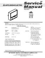
MITSUBISHI ELECTRIC

Service
Manual

2002

2002

2002

2002

2002

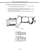
• Weight and dimensions shown are approximate.
• Design specifications are subject to change without notice.

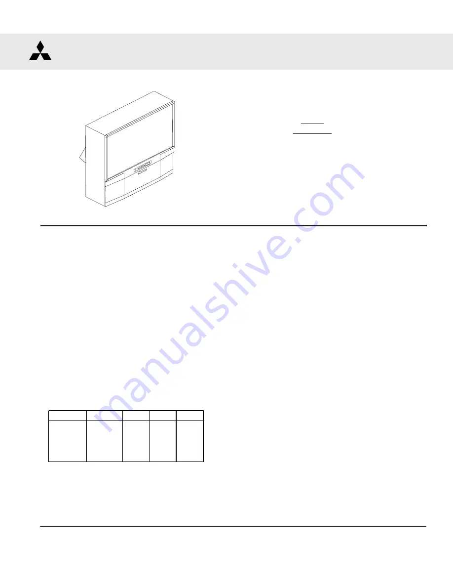
PROJECTION TELEVISION
V20B CHASSIS

SPECIFICATIONS

• Power

: AC 120V, 60Hz

240W (Except WS-73411)
275W (WS-73411 Only)

• Frequency

: VHF    54 ~ 470MHz

Range

UHF   470 ~ 806MHz

Antenna Input

: VHF/UHF 75

Ω 

unbalanced

• 

CRT Size 

: 7 inches

High Voltage

:  32.0kV (at 0A)

Weight / Cabinet Demensions

• Speaker

: [VS-A50]
  Two 4" round, full range (8

  5W)

: [WS-A48 / WS-A55 / WS-A65]
Two 5" round, full range (8

 10W)

•  Input Level

: VIDEO IN JACK (RCA Type)
  1.0Vp-p 75

 unbalanced

: AUDIO IN JACK (RCA Type)
  -4.7dBm 43k

 unbalanced

: S-VIDEO IN JACK (Y/C separate)
  Y=1.0 Vp-p C=0.286Vp-p(BURST)
   75

 unbalanced

: COMP / Y, Cr, Cb (RCA Type)
  Y=1.0 Vp-p. Cr, Cb=700mVp-p
: ATV / Y(G), Pr(R), Pb(B), H, V
  Y 1.0Vp-p with sync 75

 (RCA Type)

Pr, Pb: 700mV 75

H, V: 3.0Vp-p 75

•  Output Level

: VIDEO OUT JACK (RCA Type)
  1.0Vp-p 75

 unbalanced

: AUDIO OUT JACK (RCA 

Type)

  -4.7dBm 4.7k

 unbalanced

V20B

MODELS

W

S-A

48

V

S-A

50

WS-A55
WS-A65

Model

Weight

Height Width

Depth

VS-A50

200 lbs

50.3"

42.4"

23.6"

WS-A48

171.5 lbs

49"

44.5"

23"

WS-A55

237 lbs

50"

50.6"

26.3"

WS-A65

326.5 lbs

61.9"

59"

28.1"

Summary of Contents for VS-A50

Page 1: ...F 470 806MHz Antenna Input VHF UHF 75Ω unbalanced CRT Size 7 inches High Voltage 32 0kV at 0A Weight Cabinet Demensions Speaker VS A50 Two 4 round full range 8Ω 5W WS A48 WS A55 WS A65 Two 5 round full range 8Ω 10W Input Level VIDEO IN JACK RCA Type 1 0Vp p 75Ω unbalanced AUDIO IN JACK RCA Type 4 7dBm 43kΩ unbalanced S VIDEO IN JACK Y C separate Y 1 0 Vp p C 0 286Vp p BURST 75Ω unbalanced COMP Y C...

Page 2: ......

Page 3: ...r DiamondShieldTM Removal Installation 15 SERVICING PCBs Chassis Removal 16 PCB Locations 16 Main Components Location 16 SecondAnode Lead Removal 17 CRTREPLACEMENT CRTRemoval 17 CRT Installation 18 ELECTRICAL ADJUSTMENTS Test Equipment 20 Initial Setup 21 LED Indicator Diagnostics 22 Circuit Adjustment Mode 23 ConvergenceAdjustment Mode 24 Adjustment Items List 26 Adjustment Test Points 29 Adjustm...

Page 4: ...e RF Switch or PCB SIGNAL 43 When replacing the EEPROM 43 Quick Reference List 44 Service Parts List 45 Screen Parts List 56 CIRCUITRY BLOCK DIAGRAMS Power Supply 58 Video Color Signal Path 59 Sync Signal Path 60 Deflection HV 61 X Ray Protect 62 HV Regulation 63 Sound Signal Path 64 Convergence 65 Control Circuitry 66 Section 2 Schematic Diagrams SCHEMATIC DIAGRAMS Overall Block Diagram 1 PCB MAI...

Page 5: ... above listed models are included in this service manual for better under standing of the circuitry PCB drawings are also included for easy location of parts and test points PRODUCT SAFETY NOTICE Many electrical and mechanical parts in television receivers have special safety related characteristics These characteristics are often not evident from visual inspection nor can the protection afforded ...

Page 6: ...Radiation High voltage must be set as prescribed under the section titled Electrical Adjustments Leakage current check Before returning the receiver to the customer it is recommended that leakage current be measured according to the following methods 1 Cold Check With the alternating current AC plug removed from the AC source place a jumper across the two AC plug prongs Connect one lead of an ohm ...

Page 7: ...binet Disassembly 1 Remove the Speaker Grille by pulling forward 2 Remove the Board Front by removing screws a 3 Remove the Screen Assembly by removing screws b Disconnect all cable harnesses between the Screen Assembly and the PCB Signal 4 Lift the Screen Assembly and pull up and away from the cabinet as shown WS A48 ...

Page 8: ...oard by removing screws a b and c 2 Remove the Back Cover by removing screws e 3 Remove 4 screws d securing the Light Box Assembly 4 Be certain that all cables and connectors between the Light Box Assembly and external items are discon nected e g speaker plugs 5 Slide the Light Box Assembly out of the cabinet WS A48 ...

Page 9: ...e the Speaker Grille by pulling forward 2 Remove the Front Board by removing screws a 3 Remove the Screen Assembly by removing screws b Disconnect all cable harnesses between the Screen Assembly and the PCB Signal 4 Lift the Screen Assembly and pull up and away from the cabinet as shown VS A50 WS A55 WS A65 ...

Page 10: ...emove the Board Slide by removing screws b 3 Remove the two Board Shelves by removing screws c 4 Remove 4 screws d securing the Light Box Assembly 5 Be certain that all cables and connectors between the Light Box Assembly and external items are discon nected e g speaker plugs 6 Slide the Light Box Assembly out of the cabinet VS A50 WS A55 WS A65 ...

Page 11: ...resnel Lens in the sun This may cause fire and heat related injuries 1 Remove the screen assembly as shown in the Cabinet Disassembly procedure 2 Remove the Screen Holder by removing screws a 3 Slide the Lenticular Screen and Fresnel Lens from the Screen Frame Note When separating the Lenticular Screen from the Fresnel Lens use caution while prying the Screen and Lens apart Use a slot type screw d...

Page 12: ...njuries 1c Lenticular Screen and Fresnel Lens Removal 1 Remove the screen assembly as shown in the Cabinet Disassembly procedure 2 Remove the Top Bottom and Side Holder Screens 3 Carefully lift the Lenticular Screen and Fresnel Lens combination from the Screen Frame Assembly Note When separating the Lenticular Screen from the Fresnel Lens use caution while prying the Screen and Lens apart Use a sl...

Page 13: ... for proper tape length 2 Place the Fresnel Lens on top of the Lenticular Screen and apply pressure at the top edge to bond them together as shown in Figure 2 2 3 Reverse the disassembly procedure for that model to install the screens in the screen frame Lenticular Screen Fresnel Lens 0 16 inch Figure 2 2 Lenticular Screen Fresnel Lens Top Bottom Double Sided Tape Part LENS TAPE X inch Top Bottom ...

Page 14: ... a 3 Remove 4 screws b securing the top and bottom cabinet sections 4 Carefully lift the cabinet top and place it on the floor 5 Place the cabinet bottom in the desired loca tion 6 Reverse the procedure and mount the cabinet top on the cabinet bottom 7 Reinstall the the Screen Assembly and connect all cable harnesses between the Screen Assembly and the PCB SIGNAL Model WS A65 cabinet is assembled ...

Page 15: ...e Shield slightly away from the unit Place your hands at the points shown and gently bow the Shield toward you and remove from the unit Then re install the two clips Top Bottom Molding Clips Side Molding Clips 1 Gently insert a small screwdriver between the DiamondShield and one end of the clip to pry the clip loose 2 Remove both clips by pulling them toward you 3 Carefully insert a small screwdri...

Page 16: ...65 SERVICING PCBs Chassis Removal and PCB Locations Major Parts Locations Chassis Removal 1 Remove screw a from the Main Chassis 2 Raise the two chassis locks on the inner sides of the Lightbox Assembly and slide the chassis towards the rear ...

Page 17: ... when performing steps 1 through 4 1 Remove the Speaker Grille Front Board and Screen Assy 2 Remove the Back Board 3 Remove the Anode Lead Wire from the Flyback transformer Use the above procedure 4 Remove the PCB CRT 5 Remove 4 hex screws a retaining the Optical Unit Figure 5 1 6 Remove 4 screws b retaining the Lens Note DO NOT loosen the RED screws Doing so will break the seal between the C Elem...

Page 18: ...he CRT and the CRT Spacer causing leakage of the CRT Coolant 2 Installation of the CRT Note The replacement CRT is supplied as an assembly comprised of the CRT and the Inner Lens with the space between them filled with ethylene glycol Care should be taken during handling and installation to prevent shock from disrupting the seal or alignment between the CRT and Inner Lens Figure 5 3 Figure 5 3 Fig...

Page 19: ...and 5 2 a Position the Lens so that the Label faces the direction shown in Figure 5 7 b Install the mounting screws Figure 5 1 4 Install the PCB CRT 5 Insert the Optical Unit into the Light Box Assembly 6 Insert the Anode Lead Wire into the Flyback Transformer 7 Re clamp the Lead Wire in its original position Figure 5 6 Figure 5 7 Adjustment procedures after replacing the CRT s CRT Cut Off White B...

Page 20: ...ss otherwise specified use 10 1 probes Signal Generator both SD and HD capable Frequency Counter Direct Current Voltmeter Direct Current Power Supply Multiplex Audio Signal Generator Direct Current Ampere Meter 2 Test Signal A Monoscope Signal Note If you do not have a monoscope signal source connect the unit to a VCR and play a Monoscope alignment tape Part Number 859C568060 B Color Bar Signal Us...

Page 21: ...ass 0 5 Time Zone Eastern Lock Time N A TV Treble 0 5 Daylight Savings Time Applies Unlock Time N A TV Balance 0 5 Clock Time N A TV Surround Off Set Day N A Video Mute On TV Listen To Stereo Black Enhancement On TV Level Sound Off Closed Captions On if Mute VIDEO SETTINGS CC Background Gray TV Contrast 1 Timer Off TV Brightness 0 5 Antenna ANT A Set Time 12 00PM TV Sharpness 0 5 Channel 3 Set Day...

Page 22: ...cates the value of the MSD tens digit of the Error Code The flashing then pauses for approximately 1 2 second The LED then flashes indicating the value of the LSD ones digit of the Error Code The Error Code is repeated a total of 5 times Example If the Error Code is 24 the LED will flash two times pause and then flash four times C Error Codes The Error Code designations indicating a malfunction or...

Page 23: ...lowing pages for the listing of adjustment functions and adjustment items 1 Press the AUDIO button on a remote hand unit to select an adjustment function Each time the button is pressed the Function changes in the following sequence 2 Press the VIDEO button to select a specific Adjustment Item The Item number increases each time the VIDEO button is pressed C Changing Data After selecting an adjust...

Page 24: ...SD mode is activated If the signal source is HD 1080i the HD mode is activated 3 Activating the HD mode when no HD signal is available Activate the Factory Option Menu MENU 2 2 7 0 Use the Adjust keys to select DTV Port and press Enter to change the setting to 1080i Sequence Auto 480i 480 p 1080i Ignore any loss of sync while changing modes Exit the Option Menu Press MENU twice Select the DTV Inpu...

Page 25: ...button to select a Sub Function 2 Use the VIDEO button to select an Adjustment Item 3 Use the ADJUST buttons to change data F FINE CONV Press 4 Sub Functions This mode is used to perform Fine Raster Correction and Fine Red and Blue Convergence Adjustments There are three Sub Adjustment Functions selected with the AUDIO button FINE GREEN a Green Crosshatch is displayed for Fine Raster Corrections F...

Page 26: ...ion Range 480i 480p 1080i Adjustment 1 SCT Picture Gain control 0 63 42 42 42 Sub Contrast 2 SBRT Sub Brightness 0 63 20 20 20 Black Level 3 SCON Sub Contrast 0 15 7 7 7 Preset 4 RDRH R Drive H temp 0 63 31 31 31 White Balance 5 GDRH G Drive H temp 0 63 41 41 41 Preset 6 BDRH B Drive H temp 0 63 31 31 31 White Balance 7 CTRH R Cutoff H temp 0 63 31 31 31 8 CTGH G Cutoff H temp 0 63 31 31 31 Preset...

Page 27: ...3 12 SUB MATRIX MENU 2 2 5 7 Item Abbrev Description Range Initial 1 TNTS Main Tint Control 0 63 28 2 COLS Main Color Control 0 63 30 3 YDRS Main Y Gain 0 63 12 4 VPDS U signal DC Control 0 15 7 5 UPDS V signal DC Control 0 15 7 Data Data CONV MISC MENU 2 2 5 9 6 Item Abbrev Description Range SD HD 1 HVOL HV Adjust 0 352 150 150 2 VCNT V saw amplitude 0 127 29 29 3 VSTR V saw start timee 0 127 0 1...

Page 28: ...4 TILT Tilt Xaxis 0 0 0 0 0 0 0 0 5 HLIN Horiz Linearity 195 170 140 125 150 170 150 150 6 HWID Width 22 30 5 0 0 0 0 0 7 VKEY Vert Keystone 100 85 15 87 70 90 90 70 8 VWID Height 0 16 0 0 0 0 0 0 9 VLIN Vert Linearity 0 0 0 0 20 20 0 0 10 TBPC Top BottomPC 200 169 150 150 20 20 20 20 11 SDBW SideBow 0 0 0 0 30 30 30 30 COARSECONVBLUE MENU 2 2 5 9 5 Abbrev Description SD HD SD HD SD HD SD HD 1 HST...

Page 29: ... WS A65 Adjustment Test Point Location Test Points DT pin 3 HV Adjust DT pin 6 Ground DT pin 7 12 Volts DT pin 8 ACL JA pin 17 Main Picture Y JA pin 21 Main Color Pr JB pin 1 Sub Picture Y JB pin 3 Sub Picture Cr TP6 R G or B CRT Cathode ...

Page 30: ...or Convergence E2RESET are activated HV Circuit 1 HV Regulation Oscilloscope JA Connector pin 17 JB Connector pin 1 Color Bars Video Input Video Circuit 2 Main Sub Y Level To set picture luminance Excess or insufficient brightness 1 Supply a color bar signal to a Video Input not an RF input 2 Select the color bar signal for both the main and sub pictures 3 Connect the oscilloscope to connector JA ...

Page 31: ...o Sub PR Main PR 3 Main Sub Color Level CIRCUIT ADJUST MODE Activate MENU 2 2 5 7 Function AUDIO Item No VIDEO Adjust Data ADJUST Save Data ENTER Exit MENU twice To set the cutoff point for all three CRTs Monochrome has a color tint or incorrect brightness CRT Circuit 4 CRT Cutoff Oscilloscope TP6R TP6G TP6B 50V Div 2msec Div None Video Input Note Use the Expand mode full screen 1 Select an Extern...

Page 32: ...duce the luminance level to 25 10 Adjust Item 13 CTRL and 15 CTBL for optimum white 11 Set the data for Item 19 COL back to 31 Maximum CRT Current CRT ALL BUT 73 CURRENT 73 CURRENT RED 580 uA 900 uA GREEN 580 uA 900 uA BLUE 580 uA 900 uA CIRCUIT ADJUST MODE Activate MENU 2 2 5 7 Function AUDIO Item No VIDEO Adjust Data ADJUST Save Data ENTER Exit MENU twice To set the CRTs white level in the HD mo...

Page 33: ...0 60 70 80 90 GRADATION SCALE DC ma meter DT connector pins 7 8 Grayscale RF Input To set overall beam current to its optimum level Excess or insufficient contrast Note Activate the Expand mode full screen 1 Supply a Grayscale signal to a RF Input 2 Activate the Adjust Mode Video Chroma Function 3 Select Item 1 SCT signal level automatically reduces 4 Connect a 3ma DC meter between DT connector pi...

Page 34: ...ope Video Input Poor focus Note This adjustment must be done before Electrostatic Focus Perform this adjustment for RED GREEN and BLUE monochrome pictures 1 Supply a VIDEO signal Monoscope 2 Cover the Red and Blue Lens producing a green raster 3 Adjust the Green Lens for best focus at the center of the Monoscope pattern Note Attach a white paper to the screen center During adjustment observe the p...

Page 35: ...t Poor focus Note This adjustment must be performed after the Sub Contrast adjustment Alignment Magnet Adjustment WS 55411 WS 656411 and WS 73411 Only This adjustment must be performed before Static Focus Adjustment 1 Supply a Crosshatch with Center Dot signal to a Video Input 2 Select a Green raster using the table below 3 Roughly adjust Green Focus VR 4 Rotate Green Focus VR CCW so the center do...

Page 36: ... SKEW 0 0 0 0 0 0 0 0 4 T ILT 0 0 0 0 0 0 0 0 5 HWID 0 10 5 5 20 20 0 0 6 HLIN 0 10 15 15 0 0 10 10 7 SPCC 0 0 0 0 0 0 0 0 8 HKEY 0 0 0 0 0 17 0 0 9 TBPC 200 169 150 150 180 190 200 170 10 VKEY 0 14 0 20 0 14 15 10 11 VWID 11 17 40 30 20 30 30 30 12 VLIN 0 0 0 0 0 0 0 0 COARSECONVRED MENU 2 2 5 9 5 Abbrev SD HD SD HD SD HD SD HD 1 HSTA 50 50 50 50 50 50 50 50 2 VSTA 0 0 0 0 0 0 0 0 3 SKEW 0 0 0 10...

Page 37: ...the signal source 3 Activate the Adjustment Mode JNGL Function 4 Select and adjust each of the following items 7 VHGT so the vertical marker sum 4 1 HWD so the horizontal marker sum 7 5 Save data and Exit the Service Mode HD Mode 1 Supply an HD Monoscope signal to the DTV HD Inputs 2 Select the DTV Inputs as the signal source Input button 3 Activate the Service Mode Defl Jungle Function 4 Select a...

Page 38: ...a Cursor is displayed on the crosshatch 5 Use the Cursor to adjust for straight crosshatch lines 6 Exit the Convergence Mode HD mode 1 Supply horizontal and vertical HD sync to the DTV Inputs and select the DTV Inputs as the source Note If an HD signal is not available use the Conv HD with No Signal Procedure 2 Enter the Convergence Mode Coarse Green 3 Repeat NTSC Steps 3 through 6 in the HD mode ...

Page 39: ...d mode use the Red Centering Magnet to converge red on the green at the center of screen Correct any red tilt with the Red Deflection Yoke 7 In the Coarse Blue mode repeat Step 6 using the Blue Centering magnet and the Blue Deflection Yoke 8 Exit the Convergence mode SD mode 1 Supply an NTSC Monoscope signal to a Video Input 2 Select the Monoscope as the signal source Input button 3 Enter the Conv...

Page 40: ...green Note If center convergence shifts use red and blue Items 0 HSTA and 1 VSTA to correct the shift 6 Exit the Convergence Mode HD mode 1 Supply horizontal and vertical HD sync to the DTV Inputs and select the DTV Inputs as the source Note If an HD signal is not available use the Conv HD with No Signal Procedure 2 Repeat SD Steps 2 through 5 in the HD mode 3 Exit the Convergence mode Convergence...

Page 41: ...6 Exit the Convergence mode HD Fine Adjustment 1 Supply an HD signal sync only to the DTV inputs and select DTV with the Audio button Note If an HD signal is not available use the Conv HD with No Signal Procedure 2 Repeat SD Fine Adjustment Steps 2 through 6 in the HD mode Convergence Circuit 18 Fine Convergence NTSC None HD HD sync Video DTV Inputs CONVERGENCE MODE Activate MENU 2 2 5 9 Misc 6 Co...

Page 42: ... seconds to new chip parts 5 Avoid using a rubbing stroke when soldering 6 Take care not to scratch or damage the chip parts when soldering 7 Supplementary cementing is not required Chip Parts Removal Resistors Capacitors etc 1 Grasp the part with tweezers Melt the solder at both sides alternately and remove one side of the part with a twisting motion 2 Melt the solder at the other side and remove...

Page 43: ...for tolerance characteristics of electrical components REPLACEMENT PARTS MARK B C D F G J K Tolerance 0 1 0 25 0 5 1 2 5 10 MARK M N V X Z P Q Tolerance 20 30 10 40 20 80 20 100 0 30 10 MARK M N V X Z Tolerance pF 0 1 0 25 0 5 1 2 Replacement Part Notes When Replacing the RF Switch RF SW or the PCB SIGNAL 1 Remove the PLATE RF SW from the original component shown in the diagram at the right 2 Inst...

Page 44: ...040 DEFL YOKE WS A48 WS A55 330P276050 DEFL YOKE WS A65 453B036010 CAP ANOD SHORT RED 453B036020 CAP ANODE LONG G B MODEL ASSY CRT RED ASSY CRT GREEN ASSY CRT BLUE VS A50 251C215070 251C215080 251C215090 WS A48 251C218070 251C218080 251C218090 WS A55 251C218010 251C218020 251C218030 WS A65 251C218040 251C218050 251C218060 CRT ASSEMBLIES MODEL MIRROR LENTICULAR SCREEN FRESNEL LENS VS A50 767D072020...

Page 45: ...74HC4066AFT IC7E01 275P560010 IC ADS931E A2D CONVERTER IC7E02 275P560010 IC ADS931E A2D CONVERTER IC7E03 275P560010 IC ADS931E A2D CONVERTER IC7E10 275P769010 IC C MOS TC74AC157FT IC7E11 275P769010 IC C MOS TC74AC157FT IC7G01 275P247010 IC C MOS MB40C958VPFV IC7H00 275P799010 IC C MOS UPD85008XAGD IC7H01 270P898030 IC SI 3025LSA TL IC7H02 275P716010 IC C MOS uPD4516161AG5 A10 9NF IC7H03 275P716010...

Page 46: ...483070 DIODE RD5 1FB1 D5A35 264P045040 DIODE 1S24710M D5A36 264P045040 DIODE 1S24710M D5A37 264P521040 DIODE EU1A D5A51 262P039010 DIODE BYW96E 20 D5A52 264P899010 DIODE BYV26E D5A53 264P489010 DIODE RD16FB1 D5A54 264P622010 DIODE AL01Z D5A55 264P622010 DIODE AL01Z D5A56 264P045040 DIODE 1S24710M D5A57 264P521040 DIODE EU1A D5A58 264P045040 DIODE 1S24710M D5A60 264P488030 DIODE RD13FB2 D5A61 264P4...

Page 47: ...3 409P777080 EMI F CHIP BLM21P221S L7D04 409P777080 EMI F CHIP BLM21P221S L7D11 325C241030 COIL CHIP 10MH K L7D12 409P777020 EMI F CHIP BLM21A05 L7D13 325C241030 COIL CHIP 10MH K L7D14 409P777020 EMI F CHIP BLM21A05 L7D15 325C241030 COIL CHIP 10MH K L7E00 409P777020 EMI F CHIP BLM21A05 L7E01 409P777020 EMI F CHIP BLM21A05 L7E11 325C241030 COIL CHIP 10MH K L7E12 409P777020 EMI F CHIP BLM21A05 L7E13...

Page 48: ...0S CKD510JB1H470S LC7G11 409P876020 EMI F CHIP CNF20C470S CKD510JB1H470S LC7G12 409P876020 EMI F CHIP CNF20C470S CKD510JB1H470S LC7G13 409P876020 EMI F CHIP CNF20C470S CKD510JB1H470S LF7D00 409P901010 LP FILTER 14MHZ SMD LF7D01 409P901010 LP FILTER 14MHZ SMD LF7D02 409P901010 LP FILTER 14MHZ SMD LF7E00 409P901010 LP FILTER 14MHZ SMD LF7E01 409P901010 LP FILTER 14MHZ SMD LF7E02 409P901010 LP FILTER...

Page 49: ...0K J R5A29 103P714040 R CARBON 1 4W 39K J R5A30 103P714040 R CARBON 1 4W 39K J R5A31 103P712080 R CARBON 1 4W 1 8K J R5A32 103P713070 R CARBON 1 4W 10K J R5A33 103P463060 R METAL 1 4W 3K F R5A34 103P711000 R CARBON 1 4W 56 J R5A35 103P142010 R CARBON 1 2W 470 J R5A36 103C393010 R METAL P 3W 3 3K J 4 R5A36 103C393040 R METAL P 3W 5 6K J 1 3 R5A37 103C393010 R METAL P 3W 3 3K J 4 R5A37 103C393040 R ...

Page 50: ... J R6B01 103P711030 R CARBON 1 4W 100 J R6B02 103P713090 R CARBON 1 4W 15K J R6B03 103P464020 R METAL 1 4W 2 4K F R6B04 103P713000 R CARBON 1 4W 2 7K J R6B06 103P462050 R METAL 1 4W 1K F R6B07 103P711030 R CARBON 1 4W 100 J R6B08 103P710010 R CARBON 1 4W 10 J R6B09 103P711030 R CARBON 1 4W 100 J R6B10 103P713030 R CARBON 1 4W 4 7K J R6B11 103C194020 R METAL 3W27K J D6B11 103P712060 R CARBON 1 4W 1...

Page 51: ...02P106090 R WIRE 2W 0 12 K R9A57 103P712090 R CARBON 1 4W 2 2K J R9A58 103P145030 R CARBON 1 2W 220K J R9A59 103P710070 R CARBON 1 4W 33 J R9A61 103P713040 R CARBON 1 4W 5 6K J R9A62 103P713070 R CARBON 1 4W 10K J R9A63 103P713020 R CARBON 1 4W 3 9K J R9A66 103P712070 R CARBON 1 4W 1 5K J R9A67 103P710050 R CARBON 1 4W 22 J R9A68 103C180050 R METAL 2W 22 J R9A69 103C180050 R METAL 2W 22 J R9A70 10...

Page 52: ... 181P355000 C ELEC 50V 0 47M M C2S20 181P355000 C ELEC 50V 0 47M M C2S22 181P352030 C ELEC 16V 47M M C2S29 181P352030 C ELEC 16V 47M M C2V04 181P359060 C ELEC 50V 0 1M M C2V05 181P359060 C ELEC 50V 0 1M M C2V06 181P359060 C ELEC 50V 0 1M M C2V08 181P359060 C ELEC 50V 0 1M M C2V09 181P359060 C ELEC 50V 0 1M M C2V10 181P359060 C ELEC 50V 0 1M M C2V14 181P352040 C ELEC 16V 100M M C2V19 181P352040 C E...

Page 53: ... C CER CH50V 27P J C6G05 181P352030 C ELEC 16V47M M C6G07 142P012050 C CER B500V 0 01M K C6G10 142P012050 C CER B500V 0 01M K C6G12 155P239040 C CER CH50V 100P J C6G13 155P231090 C CER CH50V 22P J C6G14 154P405000 C CER B3KV 1000P K C6R01 154P400010 C CER B1KV 220P K C6R02 181P195050 C ELEC 350V 10M M C6R03 155P231090 C CER CH50V 22P J C6R05 181P352030 C ELEC 16V47M M C6R07 142P012050 C CER B500V ...

Page 54: ...M M C9C35 181P212060 C ELEC 16V 47M M C9C41 181P352030 C ELEC 16V 47M M C9C42 181P210040 C ELEC 6 3V 100M M C9D00 189P153040 C M POLY 250VAC 0 1M M C9D01 189P153040 C M POLY 250VAC 0 1M M CF2L00 299P128010 CERAMIC OSC CSB500F2 CF2LA0 299P128010 CERAMIC OSC CSB500F2 CF2V01 299P259010 CERAMIC OSC 2 69MHZ CF7A01 299P261010 CERAMIC OSC 27 000 MHZ SWITCHES S7L21 432P089010 SW KEY BOARD PUSH SWITCH S7L2...

Page 55: ...0MHZ X7H00 285P335050 QUARTZ CRYST 80 000MHZ Z7K01 939P617010 UNIT PREAMP GP1U283Q PRINTEDCIRCUITBOARDS 930B884005 ASSY PWB SIGNAL 234 930B884006 ASSY PWB SIGNAL 1 930B885001 ASSY PWB MAIN 2 3 930B885002 ASSY PWB MAIN 4 930B885003 ASSY PWB MAIN 1 930B886001 ASSY PWB POWER 2 4 930B886002 ASSY PWB POWER 1 930B887001 ASSY PWB TERMINAL 2 4 930B887002 ASSY PWB TERMINAL 1 935C995001 ASSY PWB CRT 935C996...

Page 56: ...388040 CAP CORNER RIGHT 10 760D639010 DIAMOND SHIELD 50 WS A55 Figure 1 1 491P125020 SCREEN LENTICULAR 55 2 491P126020 LENS FRESNEL 55 3 702A402040 CONTROL PANEL 60 4 622C060040 CLIP SCREEN TOP BOT 5 622C063040 HOLDER SCREEN BOT 6 701B457030 FRAME SCREEN S 55 7 702A388030 CAP CORNER LEFT 8 702A388040 CAP CORNER RIGHT 9 701B454010 FRAME SCREEN TOP 55 10 760D639020 DIAMOND SHIELD 55 WS A65 Figure 1 ...

Page 57: ...Figure 2 1 491P138010 SCREEN LENTICULAR 48 2 491P139010 LENS FRESNEL 48 3 622B010010 HOLDER TOP 4 635B109010 STIFFENER TOP METAL 5 622B011010 HOLDER BOTTOM 6 622B012010 HOLDER SIDE 7 598D339010 BRACKET SCREENSIDE METAL 8 751A005010 SCREEN FRAME BEZEL 9 760D639040 DIAMOND SHIELD 48 10 622B013010 CLIP SHIELD SIDE 48 Figure 2 WS A48 Screen Assembly Parts Rear View ...

Page 58: ...Page 58 MODELS VS A50 WS A48 WS A55 WS A65 POWER SUPPLY ...

Page 59: ...Page 59 MODELS VS A50 WS A48 WS A55 WS A65 VIDEO COLOR PATH ...

Page 60: ...Page 60 MODELS VS A50 WS A48 WS A55 WS A65 SYNC PATH ...

Page 61: ...Page 61 MODELS VS A50 WS A48 WS A55 WS A65 DEFLECTION HV CIRCUIT ...

Page 62: ...Page 62 MODELS VS A50 WS A48 WS A55 WS A65 X RAY PROTECT ...

Page 63: ...Page 63 MODELS VS A50 WS A48 WS A55 WS A65 HV REGULATION ...

Page 64: ...Page 64 MODELS VS A50 WS A48 WS A55 WS A65 SOUND PATH ...

Page 65: ...Page 65 MODELS VS A50 WS A48 WS A55 WS A65 CONVERGENCE CIRCUIT ...

Page 66: ...Page 66 MODELS VS A50 WS A48 WS A55 WS A65 CONTROL CIRCUIT ...

Reviews: