Page 8
MODEL: WD-52531 / WD-62531 / WD-62530
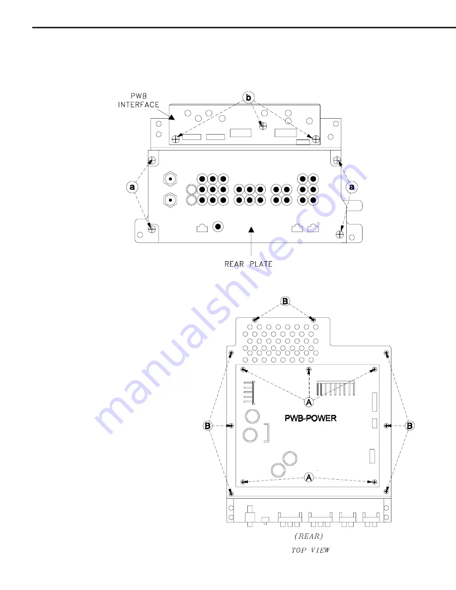
Rear Plate & PWB-INTERFACE Removal
1)
Remove 4 screws (a) and pull off the rear plate.
2)
Remove 3 screws (b) to remove the PWB-INTERFACE
PWB-POWER & Power Bracket
Removal
1)
Remove 4 screws (A) and lift PWB-
POWER from the chassis.
2)
Remove 8 screws (B) to remove the
Power Bracket.
Summary of Contents for WD-52531
Page 2: ......
Page 38: ...MODEL WD 52531 WD 62531 WD 62530 Page 38 MAIN POWER SUPPLY ...
Page 39: ...Page 39 MODEL WD 52531 WD 62531 WD 62530 LCD Engine Fan Supplies DC to DC Suppies ...
Page 40: ...MODEL WD 52531 WD 62531 WD 62530 Page 40 Analog Video Signal Path ...
Page 41: ...Page 41 MODEL WD 52531 WD 62531 WD 62530 Digital Video Signal Path ...
Page 42: ...MODEL WD 52531 WD 62531 WD 62530 Page 42 Sound Signal Path ...
Page 43: ...Page 43 MODEL WD 52531 WD 62531 WD 62530 Overall Control Circuitry ...
Page 44: ...MODEL WD 52531 WD 62531 WD 62530 Page 44 Command Input Circuitry Lamp Control Circuitry ...
Page 45: ...Page 45 MODEL WD 52531 WD 62531 WD 62530 LCD Engine Protect Circuitry Short Protect Circuitry ...
Page 46: ...MODEL WD 52531 WD 62531 WD 62530 Page 46 Auto Input Detection ...


