Page 19
MODELS: WT-46807 / WS-55807 / WS-55857 / WS-55907 /WS-65807 / WS-65857 / WS-65907 / WS-73907
CRT REPLACEMENT
1. Removal of the CRT
Caution!
High voltage should be completely discharged prior to CRT removal.
Since The CRTs receive high voltage from the HV Block, discharge
by shorting the open end of the respective high voltage cable to
chassis ground.
Note:
Refer to the Cabinet Disassembly Procedures when performing steps 1 through 4.
1.
Remove the Speaker Grille, Front Board, and Screen Assy.
2.
Remove the Back Board.
3.
Remove the Anode Lead Wire from the CR Block.
4.
Remove the PCB-CRT.
5.
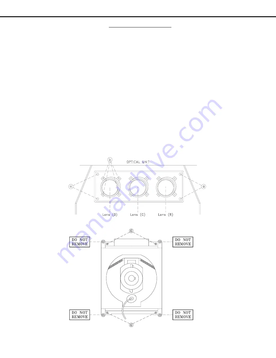
Remove 4 hex-screws "a" retaining the Optical Unit. [Figure 5-1]
6.
Remove 4 screws "b" retaining the Lens.
Note: DO NOT loosen the RED screws.
Doing so will break the seal between the
C-Element and the # 6 Lens, causing leakage of the CRT Coolant.
7.
Remove 4 screws "c" retaining the CRT. [Figure 5-2]
8.
Remove the Deflection Yoke from the neck of the CRT. [Figure 5-7]
Figure 5-2
Figure 5-1
Note:
The 4 spring-loaded screws shown
in Fig 5-2 and labeled as "DO NOT
REMOVE", should not be loosened
under any circumstance. Doing so
will break the seal between the
CRT and the CRT-Spacer, causing
leakage of the CRT Coolant.
Summary of Contents for WS-55807
Page 2: ......
Page 75: ......
Page 76: ......
Page 77: ......
Page 78: ......
Page 79: ......
Page 80: ......
Page 81: ......
Page 82: ......
Page 83: ......
Page 85: ......
Page 86: ......
Page 87: ......
Page 88: ......
Page 89: ......
Page 90: ......
Page 91: ......
Page 92: ......
Page 93: ......
Page 94: ......
Page 95: ......
Page 96: ......
Page 97: ......
Page 98: ......
Page 99: ......


