Page 25
MODELS: WS-55859 / WS-55909 / WS-65869 / WS-65909 / WS-73909
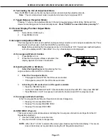
E. Terminating the Circuit Adjustment Mode
Press the MENU button on the remote hand unit twice to terminate the adjustment mode.
Note:
The circuit adjustment mode can also be terminated by turning power OFF.
F. Toggle Between Reception Modes
Pressing 3 when in the Adjustment Mode VC Function toggles between 480i, 480p, 1080i and VGA.
However data changes are not automatically saved.
Press ENTER to save data before pressing 3
.
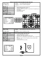
On Screen Display Position Adjust Mode
Activation
1.
Select 480i or 1080i source.
2.
Press MENU-0-1-8-8
Convergence Adjustment Mode
The Convergence mode is used to perform raster geometry correction, and convergence adjustments. These
adjustments must be made in both the SD (NTSC) and HD modes.
Note:
Before activating the Convergence mode, turn Video Mute Off. The internal crosshatch pattern
will not be displayed with Video Mute On, only a blue background is displayed.
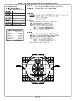
A. Convergence Mode Activation
1.
Press MENU-0-1-5-9
2.
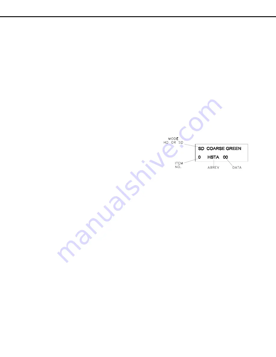
When the Convergence Mode is activated, this
display appears on a Green Crosshatch.
B. Selecting the HD or SD Mode
1.
Select the Signal Source
before entering the Con-
vergence Mode, either an NTSC or HD source.
2.
Enter the Convergence Mode
If the signal source is NTSC, the SD mode is activated.
If the signal source is HD, the HD mode is activated.
3.
Activating the HD mode when no HD signal is available
Press the DEVICE button.
Use the UP-DOWN-RIGHT-LEFT direction buttons to select the ANT-DTV, then press ENTER.
Press MENU-0-1-5-9-5 in sequence to activate the Coarse Green HD Convergence mode.
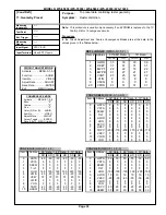
C. Convergence Mode Functions
In the Convergence Mode there are three main Functions (Categories).
Pressing 6 activates CONV MISC
Pressing 5 activates COARSE CONV
Pressing 4 activates FINE CONV
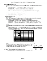
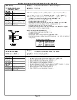
D. CONV MISC (Press 6)
This mode is used to preset data values controlling the Convergence Generator, and to perform the HV
Regulation adjustment.
1. Use the VIDEO button to select an item.
2. Use the ADJUST buttons to change data.
NOTE:
When Item 1 HVOL is selected the screen goes black except for the data display. This occurs
since a black screen is required when making the HV Regulation adjustment.
Summary of Contents for WS-55859
Page 2: ......
Page 61: ...MODELS WS 55859 WS 55909 WS 65869 WS 65909 WS 73909 Page 61 STANDBY SUPPLIES REGULATOR ...
Page 62: ...MODELS WS 55859 WS 55909 WS 65869 WS 65909 WS 73909 Page 62 SWITCHED SUPPLIES REGULATOR ...
Page 63: ...MODELS WS 55859 WS 55909 WS 65869 WS 65909 WS 73909 Page 63 DM POWER SUPPLY ...
Page 64: ...MODELS WS 55859 WS 55909 WS 65869 WS 65909 WS 73909 Page 64 VIDEO COLOR A V SWITCH CIRCUIT ...
Page 65: ...MODELS WS 55859 WS 55909 WS 65869 WS 65909 WS 73909 Page 65 PCB SIGNAL Y C PATH ...
Page 66: ...MODELS WS 55859 WS 55909 WS 65869 WS 65909 WS 73909 Page 66 SYNC PATH ...
Page 67: ...MODELS WS 55859 WS 55909 WS 65869 WS 65909 WS 73909 Page 67 DEFLECTION CIRCUIT X RAY PROTECT ...
Page 68: ...MODELS WS 55859 WS 55909 WS 65869 WS 65909 WS 73909 Page 68 SOUND CIRCUIT ...
Page 69: ...MODELS WS 55859 WS 55909 WS 65869 WS 65909 WS 73909 Page 69 CONVERGENCE CIRCUIT ...
Page 70: ...MODELS WS 55859 WS 55909 WS 65869 WS 65909 WS 73909 Page 70 CONTROL CIRCUIT ...
Page 72: ......
Page 73: ......
Page 74: ......
Page 75: ......
Page 76: ......


