-
98
-
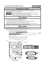
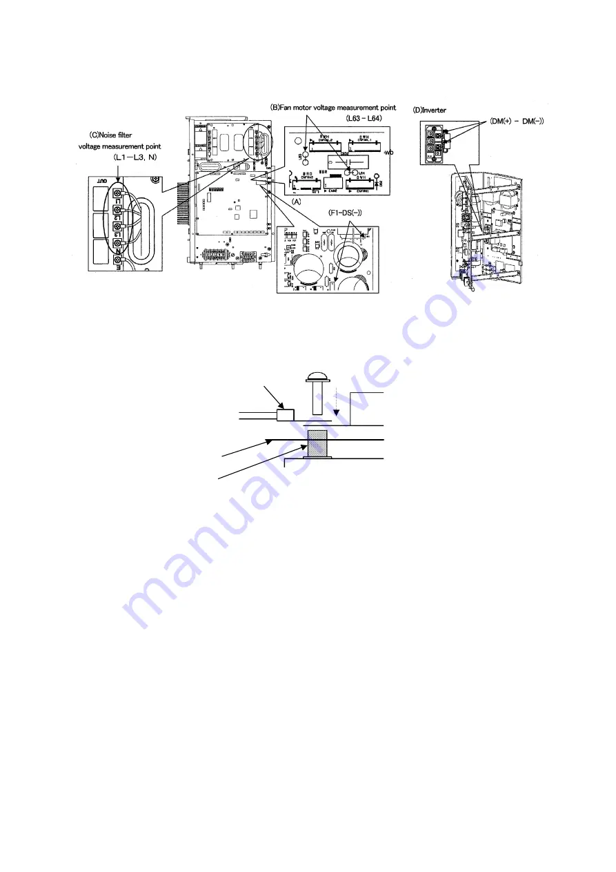
Target pwb
Pwb voltage measurement point
(F1-DS(-))
Fan motor voltage measurement point
(L63 - L64)
•
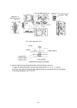
Procedure on tightening harness (snubber capacitor) and power transistor with screw.
A metallic connection binder is set in each hole of the inverter PCB of "P", "N", "U", "V", and "W"
beforehand. Then tighten the harness (snubber capacitor) and the power transistor with the screw together.
(Connect snubber capacitor with "P" and "N".)
Installation Method to Power transistor
Fig.1 Voltage Measurement Points
Terminal
Inverter PCB
Connection binder
Snubber capacitor
Harness
Power transistor
(Metallic pillar)
PCB
PCB voltage measurement point
PCB voltage measurement point
Fig.1 Voltage Measurement Points
Summary of Contents for 112KXE6
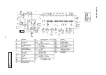
Page 105: ... 101 Model FDC335KXE6 A PCB003Z035 shows local wining ...
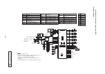
Page 134: ... 130 PJF012D003 ...
Page 135: ... 131 ...
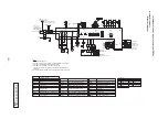
Page 139: ... 135 PJA012D751 b ...
Page 140: ... 136 ...
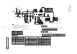
Page 206: ... 202 2 model type DIS model type HEAD ...
Page 207: ... 203 2 2 ...
Page 208: ... 204 2 2 2 2 2 ...

