-
147
-
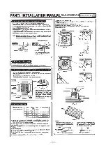
PANEL INSTALLATION MANUAL
●
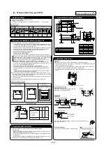
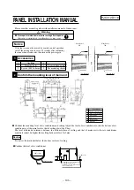
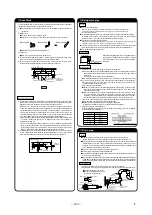
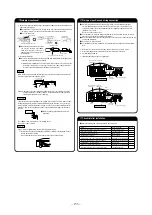
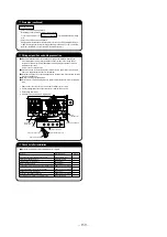
Confirm the mounting level of air conditioner and ceiling. Adjust the level of air conditioner so that the bottom of air
conditioner is at the same level as that of ceiling plate (the T-bar).
The level differential tolerance between the bottom surface of ceiling and that of main unit is that air conditioner
main unit cannot be higher than ceiling bottom surface for 5mm.
Drain hose (accessory)
mounted on site
Below 600
On-site drain up
maximum dimension
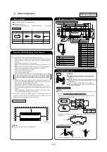
Ceiling opening dimension 740
(For wide panel)
Hanging bolt pitch 576
Control box
Panel center
Hanging bolt pitch
Ceiling opening dimension
600 (For wide panel)
For tapping
Above 85
Adjust the level of air conditioner
so that the bottom of air
conditioner is at the same level as
that of ceiling plate.
23
15
Ceiling plate
Indoor unit
Water
Transparent hose
①
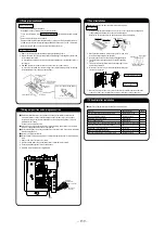
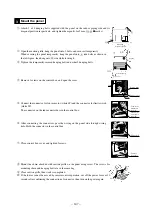
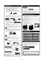
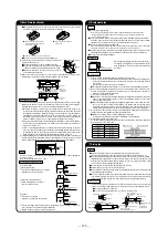
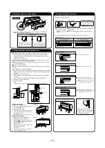
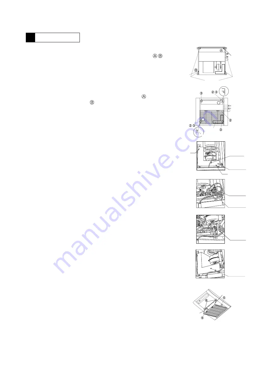
Attach 2 of 4 hanging bolts supplied with the panel on the indoor piping side and its
diagonal position respectively, and tighten them gently for 5mm. (
●
marks)
②
Open the suction grille, hang the panel onto 2 bolts, and secure it temporarily.
When securing the panel temporarily, hang the panel onto side bolts as shown in
the left figure, then hang onto side while turning it.
③
Tighten the temporarily secured hanging bolts and other 2 hanging bolts.
④
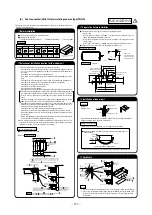
Remove 2 screws on the control box, and open the cover.
⑤
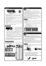
Connect the connector for louver motor (white 4P) and the connector for limit switch
(white 3P).
The connector on the indoor unit side is in the control box.
⑥
After connecting the connectors, pass the wiring on the panel side through wiring
hole. Hold the connector in the control box.
⑦
Close control box cover, and tighten 2 screws.
⑧
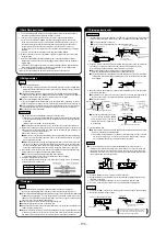
Mount the chain attached with suction grille on the panel using screw. The screws for
mounting chain and hanging bolts are in the same bag.
⑨
Close suction grille, then work is completed.
⑩
If the louver cannot be moved by remote control operation, cut off the power for over 10
seconds after confirming the connection of connector, then turn on the power again.
Confirm the mounting level of main unit
2
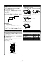
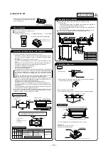
Accessories
1
1
2
3
Air filter
Hanging bolts
Screws (M4 L=8mm)
For mounting panel
For mounting chains
1
4
2
Please read this manual together with installation manual of indoor unit.
Mount the panel
3
Caution
Do not set the main unit below the bottom surface of ceiling.
●
Confirm the level of air conditioner.
Notice
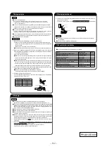
If the louver cannot be moved by remote control operation,
cut off the main power for over 10 seconds after confirming
the connection of connector, then turn on the power again.
!
A
A
A
Piping
B
Control box
Rotation direction
Warning
●
Please perform electrical work after cutting off main power.
Otherwise, electrical shock or malfunction, etc. may occur.
Short Panel
625
Suction inlet
Air outlet
Wide Panel
780
Suction inlet
650
Air outlet
For tapping
PJC012D118
Summary of Contents for 112KXE6
Page 105: ... 101 Model FDC335KXE6 A PCB003Z035 shows local wining ...
Page 134: ... 130 PJF012D003 ...
Page 135: ... 131 ...
Page 139: ... 135 PJA012D751 b ...
Page 140: ... 136 ...
Page 206: ... 202 2 model type DIS model type HEAD ...
Page 207: ... 203 2 2 ...
Page 208: ... 204 2 2 2 2 2 ...

