–
18
–
(6)
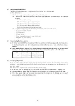
Protective control
(a)
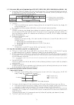
Discharge pipe temperature (Td) control
Discharge pipe temperature sensor (Tho-D1) monitors the discharge pipe temperature (Td) to avoid the rise of discharge
pipe temperature.
1)
Compressor capacity control
(i)
Start conditions
When all of following conditions are satisfied
➀
When the compressor is ON state.
➁
When it detects the discharge pipe temperature (sensed by Tho-D1) is higher than 120ºC
(ii)
Control contents
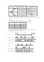
Whenever it detects the discharge pipe temperature is higher than 120ºC for 5 seconds, the capacity is decreased.
(iii)
End conditions
When any of the following conditions is satisfied
➀
When the discharge pipe temperature (sensed by Tho-D1) drops below 110ºC
➁
When the compressor is OFF state.
➂
During the defrosting control
2)
Indoor EEV slightly open control at heating stop.
Rise of discharge pipe temperature (Td) is restarined by opening the indoor EEV during heating stop.
(b)
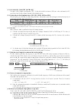
Over-current protection control (Current safe)
1)
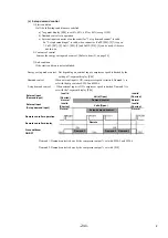
If the input current value at the inverter inlet (converter inlet L3-phase) exceeds the setting value, the compressor
speed is reduced. If the higher value persists even after the speed reduction, the speed is reduced further.
2)
This control terminates when it is lower than the reset value for 3 minutes continuously or lower than the setting
value for 6 minutes continuously.
(c)
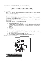
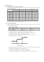
Power transistor temperature (PT) protective control
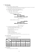
If the power transistor temperature exceeds 75°C, the compressor speed is controlled.
(7)
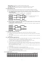
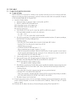
Test run
(a)
Start conditions
(i)
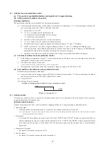
Turn ON the test run switch (SW5-1). The switch is invalid if it is turned ON before the power ON.
(ii)
Pump down switch (SW5-3) must be turned OFF.
(b)
Contents of control
(i)
Turning ON the dip switch (SW5-2) conducts cooling operation and turning OFF (SW5-2) conducts heating
operation.
1)
Cooling operation
Compressor operation frequency control is conducted by the cooling low pressure control.
2)
Heating operation
Compressor operation frequency control is conducted by the heating high pressure control.
(ii)
Test run start signal under corresponding operation mode is transmitted to all indoor units connected.
(c)
End conditions
(i)
When the test run switch (SW5-1) is turned OFF, it stops.
(ii)
When it has stopped anomalously by the error control during test run, the error is displayed in the same way as the
case of normal operation and the state of anomalous stop is kept ON even if the test run switch (SW5-1) is turned
OFF.
Speed is reduced once each minute
Retention
Release
72
75
Power transistor temp. (°C)
Summary of Contents for 112KXE6
Page 105: ... 101 Model FDC335KXE6 A PCB003Z035 shows local wining ...
Page 134: ... 130 PJF012D003 ...
Page 135: ... 131 ...
Page 139: ... 135 PJA012D751 b ...
Page 140: ... 136 ...
Page 206: ... 202 2 model type DIS model type HEAD ...
Page 207: ... 203 2 2 ...
Page 208: ... 204 2 2 2 2 2 ...


