background image

19

 –

(B)

Optional controls

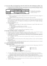
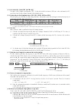
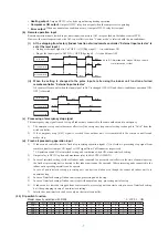
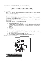
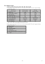
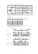
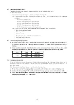
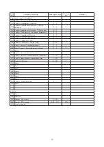
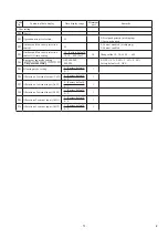
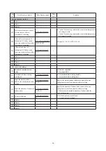
•  Functions of outdoor PCB connector CNS1, CNS2, CNG1, CNG2 and CNZ1

CNS1 connector :   

 By changing the allocation of external input functions [P07- X ] on the 7-segment, following 

functions can be selected.


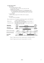
 CNZ1 connector : By changing the allocation of external output functions [P06- X ] on the 7-segment, following 

functions can be selected.

Function No. X

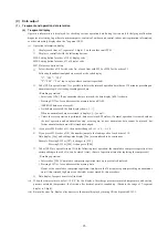
CNS1 short circuited

CNS1 open

“0” : External operation input

Operation permission

Operation prohibition

“1” : Demand input Invalid Valid
“2” : Forced cooling / heating input

Heating

Cooling

“3” : Silent mode input 1 Valid Invalid
“4” : Oil return control inpu t                                                      ON                                                      OFF
“5” : Outdoor fan snow guard control input

Valid

Invalid

“6” : Test run external input 1

Test run start

Normal operation

“7” : Test run external input 2 Cooling test run Heating test run
“8” : Silent mode input 2

Valid

Invalid

“9” : 2-step demand input                                                         Invalid                                                  Valid
* [P07] for CNS1, [P08] for CNS2, [P09] for CNG1 and [P10] for CNG2

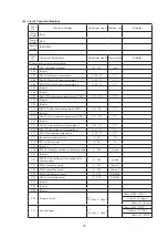
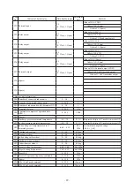
“0” : Operation output
“1” : Error output
“2” : Compressor ON cutput
“3” : Fan ON output
“4”   : Oil return operation output
“5” : High pressure control output for activating splaying system
“6 – 9” : Spare

*

   #

Summary of Contents for 112KXE6

Page 1: ...KXE6 45KXE6 56KXE6 FDU71KXE6 90KXE6 112KXE6 140KXE6 224KXE6 280KXE6 FDFU28KXE6 45KXE6 56KXE6 71KXE6 FDTW28KXE6 45KXE6 56KXE6 71KXE6 90KXE6 112KXE6 140KXE6 FDK22KXE6 28KXE6 36KXE6 45KXE6 56KXE6 71KXE6 FDTQ22KXE6 28KXE6 36KXE6 FDFL28KXE6 45KXE6 71KXE6 FDTS45KXE6 71KXE6 FDE36KXE6A 45KXE6A 56KXE6A 71KXE6A 112KXE6A 140KXE6A INDOOR UNIT KX6 series Heat pump type Manual No 09 KX SM 125 SERVICE MANUAL Reg...

Page 2: ... 126 5 1 Installation of indoor unit 126 a Ceiling cassette 4 way type FDT 127 b Ceiling cassette 4 way compact type FDTC 132 c Ceiling cassette 2 way type FDTW 137 d Ceiling cassette 1 way type FDTS 140 e Ceiling cassette 1 way compact type FDTQ 143 f Duct connected High static pressure type FDU 148 g Duct connected Middle static pressure type FDUM 154 h Duct connected Ultra thin Low static press...

Page 3: ...Pull the cover downward to open it All displays are described in the liguid crystal display for explanation The figure below shows the remote control with the cover opened Installation of remote control DO NOT install it on the following places in order to avoid malfunction 1 Places exposed to direct sunlight 2 Places near heat devices 3 High humidity places 4 Hot surface or cold surface enough to...

Page 4: ...d by one tap That tap is retained for 3 minutes after changing the indoor fan tap 3 If the thermostat OFF is established during the above control the indoor fan tap at the thermostat ON is retained so far as the thermostat is turned OFF 4 After stopping the cooling operation the indoor unit continues to run at Lo for 15 seconds b When the humidity sensor is provided FDT Series only Optional 1 Oper...

Page 5: ...ost control a Control 1 When the indoor heat exchanger temperature detected with ThI R1 or R2 drops to 35 C or lower indoor fan is changed to the lower tap at each setting 2 During the hot keep operation the louver horizontal control signal is transmitted b Ending condition When the indoor fan is at the lower tap at each setting it returns to the set airflow volume as the indoor heat exchanger tem...

Page 6: ...nize the louver position Note 1 If you press the Louver button the swing motion is displayed on the louver position LCD for 10 second The display changes to the Auto wind direction display 3 seconds later b Automatic louver level setting during heating While hot start operation and heating thermostat OFF operation the louver keeps the level position In order to prevent the cold draft whether the a...

Page 7: ...ndoor PCB is ON state it enters the mode of operation check drain pump test run It is ineffective prohibited to change the switch after turning power on b When the communication with the remote controller has been established within 60 seconds after turning power on by the dip switch SW7 1 ON it enters the operation check mode Unless the remote controller communication is established it enters the...

Page 8: ...turned ON OFF based on the setting temperature of thermostat However when the thermostat OFF is likely to occur earlier because the unit is installed in a condition that warm air tends to accumulate near the ceiling the setting can be changed by using the indoor function of wired remote controller Heating room temperature compensation Since the compressor is turned ON OF at one of the setting temp...

Page 9: ... emergency stop E 63 signal is received from outdoor unit it is transmitted to the remote controller and makes stop d Fresh air processing operation input 1 If indoor unit controller receive fresh air processing operation signal 1 or fresh air processing stop signal from remote controller it output ON signal or OFF signal from CnD connector respectively 1 Operation switch ON at interlock setting a...

Page 10: ...stored in memory regardless of whether the power failure compensation setting is valid or invalid and silent mode setting is cancelled regardless of whether the power failure compensation setting is valid or invalid Running or Stopping status just before power failure If it had been operating under OFF timer mode or simple timer mode memorzed status is as stopping At the recovery of power the time...

Page 11: ...y open Super cooling coil electronic expansion valve EEVSC Opening Angle Control Fully closed Fully closed Fully closed Fully closed Fully closed Solenoid valve SV1 oil return 〇 〇 〇 Solenoid valve SV6 fluid return 〇 〇 〇 〇 〇 Solenoid valve SV11 gas bypass 〇 Crankcase heater CH 〇 〇 〇 〇 〇 〇 Note 1 It means 〇 ON OFF 〇 〇 ON or OFF 2 This shows the state of output when all indoor units are under the sam...

Page 12: ...sor iii End conditions When all of following conditions are satisf ied It has elapsed 15 seconds after the start of this control Meaning of marks 52X1 52X2 Solenoid for compressor CM Compressor EEVH Heating electronic expansion valve EEVSC Subcooling coil electronic expansion valve SV6 Solenoid valve Oil return ON 15 seconds 6 seconds Normal control Normal control Initial opening Initial opening 3...

Page 13: ...s according to the sequence shown below iii End conditions End of sequence Meaning of marks CM Heating 15 seconds 3 minutes Initial speed Normal control Initial opening Cooling Any state FMo1 FMo2 20S EEVH EEVSC OFF Fully open Fully closed Fully closed Time Start conditions established OFF ON Any state Any state CM Compressor EEVH Heating electronic expansion valve FMo1 FMo2 Fan motor EEVSC Subcoo...

Page 14: ...i End conditions End of sequence Note 1 It is fully closed till the end of 3 minute delay after the automatic reset Meaning of marks CM FMo1 FMo2 20S EEVH EEVSC ON Heating Cooling 15 seconds 3 minutes Initial opening Fully closed Time Start conditions established Normal control Initial speed Fully closed OFF OFF Fully open Any state Any state Any state CM Compressor EEVH Heating electronic expansi...

Page 15: ...ting till reaching the lower limit frequency after 4 way valve switching safeguard operation has elapsed 1minute the target frequency is changed to that of 1minute later from the lower limit frequency During this control the target frequency is increased at a rate of 5Hz minute from the lower limit frequency Note The starting point of this control is the completion point of inverter start 10Hz Ite...

Page 16: ...om the lower limit frequency For 18 minutes after starting the starting point of this control is the completion point of inverter start 10 Hz From 18 minutes to 24 minutes it is increased at a rate of 5 Hz minute End conditions When either one of the following conditions is established a This frequency up control will end when the cumulative operation time after starting becomes 24 minutes If the ...

Page 17: ...detected HP 1 5 MPa for 1 minute continuously the fan speed is dropped by one tap Control range of fan speed is 1th 8th speeds iii When states under this control change from HP 3 3 MPa to HP 3 3 MPa the fan speed is changed preferentially to the followings After the change it returns to the normal control When the outdoor air temperature 30ºC it changes to 7th or higher speed When the outdoor air ...

Page 18: ...r fan heating control The fan speed control is performed based on the low pressure detected with PSL during heating operation i Initial fan speed is 6th speed ii Speed is changed depending on the low pressure value When it is detected LP 0 75 MPa for 30 seconds continuously the fan speed is raised by 1 tap When it is 0 75 MPa LP 0 85 MPa the present fan speed is maintained When it is detected LP 0...

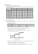
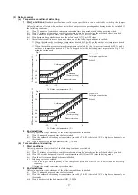
Page 19: ... 19 21 25 20 15 6 Without J15 Cold region specification With J15 SST Suction pressure saturated temperature C Fig 2 Cold region Standard Factory setting Defrost start zone 6 10 19 23 25 29 20 15 6 Without J15 Cold region specification With J15 2 End conditions Defrosting operation stops when any of the following conditions is satisfied i When 12 minutes has passed since defrost started ii When the...

Page 20: ...on the speed is reduced further 2 This control terminates when it is lower than the reset value for 3 minutes continuously or lower than the setting value for 6 minutes continuously c Power transistor temperature PT protective control If the power transistor temperature exceeds 75 C the compressor speed is controlled 7 Test run a Start conditions i Turn ON the test run switch SW5 1 The switch is i...

Page 21: ...eration prohibition 1 Demand input Invalid Valid 2 Forced cooling heating input Heating Cooling 3 Silent mode input 1 Valid Invalid 4 Oil return control input ON OFF 5 Outdoor fan snow guard control input Valid Invalid 6 Test run external input 1 Test run start Normal operation 7 Test run external input 2 Cooling test run Heating test run 8 Silent mode input 2 Valid Invalid 9 2 step demand input I...

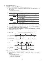
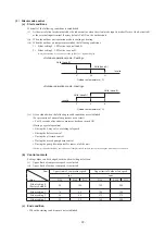
Page 22: ...is desplayed on the LCD of remote controller and is transferred to optional centralised controller 4 When the control comand from remote controller is not accepted Under the condition of the system all stop status by external input Center is dispalyed See Item 5 mentioned below 5 CnS1 performs the following operations depending on the short circuit or open of the jumper wire J13 In case of pulse i...

Page 23: ...io can be switched with the dip switches SW4 5 4 6 on the outdoor PCB SW4 5 SW4 6 demand switching 0 Open 1 Short circuit Factory default is open SW4 5 SW4 6 Compressor Out put 0 0 80 1 0 60 0 1 40 1 1 0 5 CnS1 performs the following operations depending on the short circuited or open of the jumper wire J13 In the case of pulse input the pulse width is 500ms or larger J13 Short circuit ON Short ci...

Page 24: ...al input compressor speed is limited by the setting of 7 segment display P0 Demand control When external input is ON compressor speed is limited Demand is set with the dip switches SW 5 andSW 6 step demand control When external input is ON compressor speed is limited Demand is set with the 7 segment display P0 Demand Demand control is done by the compressor output set with SW 5 and SW 6 Demand Dem...

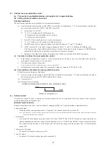
Page 25: ...when the following invalid conditions are established For prevention of anomalous pressure rise at start For 30 seconds after either compressor has been turned ON During a special operation During the 4 way valve switching safeguard During the defrost control During the oil return control During the moved pump down control During the pump down control for removal of the unit Note Any controls affe...

Page 26: ...eable from 10 to 600 seconds by P03 During this snow protection control the compressor s magnetic contactor 52X1 52X2 is ON d End conditions of outdoor fan snow protection control When folowing conditions are established i Snow protection control setting is invalid P02 0 or outdoor air temperature 5 C and external input of outdoor fan snow protection control OFF P07 5 and CnS1is opend ii Compresso...

Page 27: ...1 equipped with short circuit pin is shorted or opened so as to forcibly determined whether the indoor unit is operated for cooling or heating b If any operation mode other than the forcible mode is commanded from indoor unit the mode unmatch message is displayed on the remote controller or others and operation enters in the FAN mode SW3 7 CnG1 Operation ON Open Cooling only Close Heating only 7 E...

Page 28: ...red LED and green LED on the outdoor PCB flash continuously 7 segment display shows PdS Channel 0 at the code display area iii During the pump down operation control the protective controls excluing low pressure protective control anomalous low pressure control and pressure ratio protection control and the error detection control are effective iv The sub cooling coil expansion valve EEVSC closes f...

Page 29: ...ell Unless the reset operation is performed data are retained Therefore if normal operation is resumed without the reset operation and an anomalous stop occurs again no new anomalous data cannot be retained but former anomalous data are still retained unchanged If you press SW8 order of 1 the number changes 0 1 2 9 0 If you press SW9 order of 10 the number jumps to the leading code of each order o...

Page 30: ...ton input is done for 10 seconds after change to C00 it changes to the display of automatically according to the precedence Display switching Special display is the display other than CXX When special display occurs Special display reset or button operation Button operation Button operation No operation for 10 seconds If the special display is reset in the meanwhile it remains as CXX CXX C99 Autom...

Page 31: ...e C12 Tho P1 Power transistor temperature CM1 L 5 136 1 C C13 Spare C14 Tho SC Sub cooling coil temperature 1 L 18 73 1 C C15 Tho H Sub cooling coil temperature 2 L 25 73 1 C C16 Tho S Suction pipe temperature L 25 73 1 C C17 Inverter secondary current 0 50 1A C18 CT1 CM1 current 0 50 1A C19 Spare C20 EEVH1 Heating expansion valve opening angle 0 500 1 pulse C21 Spare C22 EEVSC Sub cooling coil ex...

Page 32: ...oor units 0 200 1 C42 Number of indoor units with thermostat ON 0 50 1 C43 Required Hz total 0 999 1Hz C44 Cumulative compressor operation time CM1 0 655 100h C45 Spare C46 Discharge pressure saturated temperature 50 70 0 1 C Range unable to display 10 C or under is in the unit of 1 C C47 Suction pressure saturated temperature 50 30 0 1 C Range unable to display 10 C or under is in the unit of 1 C...

Page 33: ... 0 5 1 C77 Counter Current cut CM1 0 4 1 C78 Counter Compressor 1 starting failure 0 20 1 C79 Counter Inverter 1 comunication error 0 4 1 C80 Spare Counter Power transistor 1 overheat 0 4 1 C81 Spare C82 Counter Inverter 1 desynchronism error 0 4 1 C83 Counter Inverter 1 comunication error cumulative 0 127 1 C84 Counter Indoor outdoor comunication error 0 255 1 C85 Counter CPU reset 0 255 1 C86 Sp...

Page 34: ...g 30 Factory default 10 30 600 Sec 30 Changes like 10 30 60 90 600 P04 OFF 000 040 060 080 0 OFF 1 0 2 40 3 60 4 80 Factory default is 0 OFF P05 Silencing mode setting 0 Factory default 0 9 1 P06 Allocation of external output CnZ1 0 Factory default 0 9 1 P07 Allocation of external input CnS1 0 Factory default 0 9 1 P08 Allocation of external input CnS2 1 Factory default 0 9 1 P09 Allocation of ext...

Page 35: ...ng 0 Factory default 0 9 1 P22 Spare P23 Spare P24 Spare P25 Spare Newsuper link setting P30 Superlink communication status 0 1 0 Previous superlink 1 New superlink P31 Automatic address setting start input 0 Factory default 0 1 0 Automatic address setting standby 1 Automatic address setting start P32 Input the starting indoor address for automatic address setting 1 Factory default 1 127 1 Specify...

Page 36: ...ss Ascii 2 bytes 00 3F Indoor address 16 units Ascii 2 bytes 16 units 40 7F Indoor capacity 16 units Ascii 3 bytes 16 units 022 280 Outdoor unit composition Outdoor unit capacity data Remarks Single type Example 10HP S10 S Display with Horse Power of single type iv Error retention and monitoring data Code No Write contents Record data Data write range Unit of write Number of bytes Contents 00 Indo...

Page 37: ...information 15 Number of connected indoor units 0 127 1 unit 1 16 Capacity of connected indoor units 0 65535 2 17 Number of indoor units with thermostat ON 0 255 1 unit 1 18 Total capacity of indoor units with cooling thermostat ON 0 65535 2 19 Total capacity of indoor units with heating thermostat ON 0 65535 2 20 Operation mode 0 2 1 0 Stop 1 Cooling 2 Heating 21 Inverter CM1 actual operation fre...

Page 38: ...ge 0 600min 10 hour PCB hardware input 48 External input 1 Bit0 63H1 0 Open 1 Short circuit Bit1 Spare 0 Open 1 Short circuit Bit2 CNS1 0 Open 1 Short circuit Bit3 CNS2 0 Open 1 Short circuit Bit4 CNG1 0 Open 1 Short circuit Bit5 CNG2 0 Open 1 Short circuit Bit6 Spare 0 Open 1 Short circuit Bit7 Spare 0 Open 1 Short circuit 49 Dip SW SW3 1 Bit0 SW3 1 0 OFF 1 ON Bit1 SW3 2 0 OFF 1 ON Bit2 SW3 3 0 O...

Page 39: ... OFF 1 ON Bit1 20S 0 OFF 1 ON Bit2 CH1 0 OFF 1 ON Bit3 SV1 0 OFF 1 ON Bit4 SV6 0 OFF 1 ON Bit5 SV11 0 OFF 1 ON Bit6 Spare 0 OFF 1 ON Bit7 Spare FMC1 2 0 OFF 1 ON 55 Relay output 1 Bit0 Operation output CnH 0 OFF 1 ON Bit1 Error output CnY 0 OFF 1 ON Bit2 External output CnZ 0 OFF 1 ON Bit3 Spare 0 OFF 1 ON Bit4 Spare 0 OFF 1 ON Bit5 Spare 0 OFF 1 ON Bit6 Spare 0 OFF 1 ON Bit7 Spare 0 OFF 1 ON Rela...

Page 40: ...NV1 communication error counter cumulative 0 255 1 1 84 Spare Control status INV1 power transistor overheat error counter 0 4 1 1 85 Control status INV1 rotor lock error counter 0 127 1 1 Setting value display 86 Operation priority switching outsoor fan snow protection control 0 1 1 0 First push priority 1 Last push priority 87 Outdoor fan snow protection control 0 1 1 0 Invalid 1 Valid 88 Outdoor...

Page 41: ...ature 1 Outdoor heat exchanger temperture 1 2 Outdoor heat exchanger temperture 2 3 Discharge pipe temperature sensor 1 CM1 4 Suction pipe temperature sensor 5 Sub cooling temperature sensor 1 liquid side 6 Sub cooling temperature sensor 2 gas side 7 Under dome temperature sensor 1 8 Power transistor temperature sensor 1 9 Active filter temperature sensor 10 High pressure sensor 11 Low pressure se...

Page 42: ...4 4 SW4 5 Demand ratio selection See following table SW4 6 Demand ratio selection See following table SW5 5 SL selection New SL Previous SL J11 Power supply voltage selection Open J12 Power supply voltage selection Open J13 External input Level Pulse Level Pulse J14 Defrost reset temperature Normal Intensive J15 Defrost start temperature Normal Cold region Normal Cold weather region Note 1 Jumper ...

Page 43: ...g etc Is the failure related to any hardware parts SV main body coil capillary check valve sensor etc Is it a major component Compressor inverter PCB and outdoor DC fan motor Is it a failure of electrical component Error on indoor unit or outdoor unit Indoor unit Outdoor unit Is the remote controller connected Was the power supply reset after the error occurred Check and write down the momentary d...

Page 44: ...ollowing check Be sure to check both fan motor 1 and 2 After completion of checking both fan motor 1 and 2 replace the anomalous fan motor Turn the power ON power circuit breaker ON and start operation with the test run SW Check between 1 and 2 of CNA2 on the control PCB to see if DC 15V is detected Be sure to wait for 3 minutes after turning the power circuit breaker off Disconnect the fan motor ...

Page 45: ...rmistor wire breakage 77 E38 E38 Outdoor air temperature thermistor anomaly Tho A Thermistor wire breakage 78 E39 E39 1 Discharge pipe temperature thermistor anomaly Tho D1 Thermistor wire breakage 79 E40 E40 High pressure anomaly 63H1 1 activated System error 80 E41 E51 E41 E51 1 Power transister overheat System error 81 E42 E42 1 Current cut CM1 System error 82 E43 E43 1 E43 2 Excessive number o...

Page 46: ...ifying or heating operation from remote controller Note 1 Outdoor 35ºC Indoor 27ºCDB 19ºCWB It is normal This unit is designed to start in the soft start mode by detecting the compressor under dome temperature when it restart after power reset It is necessary to replace to higher capacity unit or to install additional unit Compressor refrigerant oil protective control at starting is activated For ...

Page 47: ...ing operation from remote controller Note 1 Outdoor 7ºC Indoor 20ºC It is normal This unit is designed to start in the soft start mode by detecting the compressor under dome temperature when it restart after power reset It is necessary to replace to higher capacity unit or to install additional unit Compressor refrigerant oil protective control at starting is activated For the contents of control ...

Page 48: ... resistance may drop to a few MΩ because of refrigerant migrated in the compressor When the earth leakage breaker is activated at lower insulation resistance check the following points 6 hours after power ON check if the insulation resistance recovers to normal When power ON crankcase heater heat up compressor and evaporates the refrigerant migrated in the compressor Check if the earth leakage bre...

Page 49: ...eness Prevent the vibration from transmitting to wall and etc by fixing pipes on the wall tightly or wrapping rubber cushion around the pipe which goes through the hole in the wall or applying other appropriate means Strength of ceiling wall floor etc may be insufficient Review the installation place or apply reinforcement to increase the strength Check for leaning of installed unit or incorrect m...

Page 50: ...s through inside of piping of air conditioner It is likely to occur particularly during cooling or defrosting in the heating mode It is normal The noise vibration occurs when the refrigerant starts or stops flowing It is normal When the defrosting starts or stops during heating mode the refrigerant flow is reversed due to switching 4 way valve This causes a large change in pressure wich produces a...

Page 51: ...ion of air nitrogen etc In such case it is necessary to recover refrigerant vacuum dry and recharge refrigerant Since there could be many causes of noise vibration the above may not cover all In such case check the conditions when where how the noise vibration occurs according to following check points and ask our consultation Indoor outdoor unit Cooling heating fan mode Startup stop during operat...

Page 52: ...g YES NO Does the louver link press LS till crick sound can be heard NO NO YES NO NO YES In cases of FDTW FDTS and FDTQ Does the louver operate when power on Note 1 LM Louver motor 2 LS Limit switch YES NO NO NO NO YES YES Operate after waiting for more than 1 minute It is normal if LM can be stopped by pressing LS two times In cases of FDT FDTC FDE and FDK Check the remote controller whether it i...

Page 53: ... between of CNW0 OK Is DC5V detected between of CNW2 Is power supply to FM LM and etc OK Note 1 FDT and FDTC series F200 F201 Other than FDT and FDTC Fuse between wires 1 2 3 4 Other than FDT and FDTC series FDT and FDTC series Is DC18V or higher detected between Red Red CNW2 at the transformer secondary side Outdoor Noise filter PCB anomaly Replace it Wrong wiring or broken wires between outdoor ...

Page 54: ...dary side Is DC18V detected between of CNW2 Disconnect the remote controller wires NO Is DC15V or higher detected between X Y of indoor unit terminal block Other than FDT and FDTC Series FDT and FDTC Series YES YES YES YES NO NO YES NO NO Correct it Replace wires Replace remote controller Indoor power PCB anomaly Replace it Indoor control PCB anomaly Replace it Replace transformer Indoor control P...

Page 55: ...ise filter PCB Connect wires correctly Indoor control PCB anomaly Replace it Indoor outdoor control PCB anomaly Replace it Remote controller anomaly Replace it Breakage of wires for remote controller Replace it Correct the connecting wires between indoor and outdoor units Outdoor control PCB anomaly Replace it Breakage of connecting wire Noise Indoor control PCB anomaly Replace it 2 Error detectio...

Page 56: ... t there any short circuit between phases of noise filter Isn t there any crack or damage on power transistor module or diode stack Isn t there any anomaly on reactor Replace noise filter Replace reactor Replace inverter PCB Replace fuse 2 Error detection method 3 Condition of error displayed 4 Presumable cause Fuse blown Noise filter anomaly Anomalous connection of wire between PCBs Indoor contro...

Page 57: ...Is The fuse on indoor control PCB OK Is AC18V or higher is detected between Red Red at secondary side of indoor transformer 1 Is DC10 11V between X Y at indoor control PCB side when removing remote controller Note 1 except FDT and FDTC Fuse blown Replace fuse Transformer anomaly Remote controller wire short circuited Remote controller anomaly Indoor control PCB anomaly Remote controller anomaly Br...

Page 58: ...between L1 L2 L2 L3 L3 L1 respectively at outdoor terminal block Is AC220 240V detected between L N at indoor teminal block NO NO NO NO NO YES YES YES YES YES YES A WAIT Refer next page Indoor control PCB anomaly Replace it Indoor control PCB anomaly Replace it Remote controller anomaly Replace it Breakage of wires for remote controller Replace it Correct the connecting wires between indoor and ou...

Page 59: ...there any anomaly on outdoor fan motor Once turn OFF the breaker and turn ON it again at 3 minute after power OFF Does it become normal Check inverter before replacement of 52C NO NO NO NO NO NO YES YES YES YES YES YES A B Normal Malfunction by temporary noise Refer next page Replace noise filter Connect the connecting wire properly Correct connection In case of breakage of wire replace it Outdoor...

Page 60: ... Replace electrolytic capacitor Replace reactor Isn t there any short circuit between phases at input terminal of inverter PCB Isn t there any crack or damage on power transistor module or diode stack Isn t there any anomaly on reactor Isn t there any anomaly on electrolytic capacitor YES YES YES YES YES NO NO NO NO NO B 2 Error detection method 3 Condition of error displayed 4 Presumable cause Fu...

Page 61: ... detected at remote controller terminal Is DC10V or higher between X Y wires detected when removing remote controller Are connecting wires between indoor and outdoor units connected properly Remote controller anomaly Remote controller anomaly Correct connecting wire Indoor control PCB anomaly 2 Error detection method 3 Condition of error displayed 4 Presumable cause Fuse blown Noise filter anomaly...

Page 62: ...the remote controller displays Internal check ON even after 3 minutes Reset power supply 2 1 NO Malfunction by temporary noise Check peripheral environment Indoor control PCB anomaly Replace it Remote controller anomaly Replace it 2 Error detection method When normal communication between remote controller and indoor unit is interrupted for more than 2 minutes Detectable only with the remote contr...

Page 63: ...ly is reset addresses will not be confirmed YES NO YES NO YES NO Review number of connected units Correct indoor unit address setting Implement test run Replace indoor control PCB Before replacement confirm whether the rotary switch for address setting is not damaged It was experienced that No 5 on rotary switch was not recognized 2 Error detection method More than 129 indoor units are connected i...

Page 64: ...n both cases check signal wires between indoor outdoor units locally YES Is the outdoor unit address set on the indoor unit OK YES Is the LED on indoor control PCB OK YES Is protective fuse for the super link circuit blown NO Does E3 E5 occurs YES NO NO NO YES YES NO NO Temporary malfunction by noise Identify the source of noise and correct it Change to spare circuit Indoor control PCB anomaly Rep...

Page 65: ...ge of signal wires between indoor and outdoor units YES NO YES NO YES NO In case that indoor red LED flashes 2 times Repair signal wires Repair signal wires Go to the diagnosis of WAIT 1 Unit is normal Malfunction by temporary noise etc Outdoor control PCB anomaly Network communicaion circuit anomaly Replace it Unit is normal Malfunction by temporary noise etc 2 Error detection method When the com...

Page 66: ...ance characreristics of indoor heat exchanger temperature thermistor Thi R1 R2 R3 5kΩ at 25ºC Temperature ºC Insert the connector securely Replace thermistor Thi R Replace indoor control PCB 2 Error detection method Detection of anomalously low temperature resistance of Thi R1 R2 R3 3 Condition of error displayed If 50ºC or lower is detected for 5 seconds continuously compressor stops After 3 minu...

Page 67: ...s to prove any poor connection 15 10 5 0 10 30 40 20 50 Temperature thermistor resistance k Ω Temperature C 5kΩ at 25 C Insert the connector securely Replace thermistor Thi A Replace indoor control PCB 2 Error detection method Detection of anomalously low temperature resistance of Thi A 3 Condition of error displayed If 50 C or lower is detected for 5 seconds continuously compressor stops After 3 ...

Page 68: ...drain pipe slop OK NO YES NO YES NO NO Check float switch Check the connection of CNI If it is loose connect it securely Replace indoor control PCB Check optional equipment Correct setting to Humidifier drain motor interlock Indoor control PCB anomaly Replace it Check the wiring of drain motor Correct it Check drain motor 2 Error detection method Float switch is activated 3 Condition of error disp...

Page 69: ... model 5 Troubleshooting All models Diagnosis Countermeasure Aren t more than 17 indoor units connected to one remote controller NO YES Remote controller anomaly Replace it Reduce to 16 or less units 2 Error detection method When it detects more than 17 of indoor units connected to one remote contorller 3 Condition of error displayed Same as above 4 Presumable cause Excessive number of indoor unit...

Page 70: ...splayed Same as above 4 Presumable cause Mistake in address setting for indoor unit Note Address setting method list Figures in are for Previous superlink models Models for new superlink protocol Models for Previous superlink protocol Indoor unit address setting Outdoor unit address setting Indoor unit address setting Outdoor unit address setting Indoor unit No SW Outdoor unit No SW Outdoor unit N...

Page 71: ...r Replace the fan motor Check power supply voltage Replace fan motor and power PCB Replace fan motor If the anomaly persists after replacing the fan motor replace the indoor control PCB Malfunction by temporary noise 2 Error detection method Detected by revolution speed of indoor fan motor 3 Condition of error displayed When actual revolution speed of indoor fan motor drops to lower than 200min 1 ...

Page 72: ...ter Replace fan motor Replace fan motor and power PCB Replace fan motor If this anomaly persists after replacing the fan motor replace indoor control PCB Malfunction by temporary noise 2 Error detection method Detected by revolution speed of indoor fan motor 3 Condition of error displayed When actual revolution speed of indoor fan motor drops to lower than 200min 1 for 30 seconds continuously the ...

Page 73: ...ayed Same as above 4 Presumable cause Mistake in SW7 1 setting Due to forgetting to turn OFF SW7 1 after indoor operation check Note Indoor operation check drain pump check mode If the power is ON after SW7 1ON indoor operation check drain pump check mode can be established 1 When the communication between remote controller and indoor PCB is established 15 seconds after power ON it goes to indoor ...

Page 74: ...s again within 60 minutes after the initial detection 4 Presumable cause Anomalous connection of remote controller temperature thermistor Remote controller temperature thermistor anomaly Remote controller PCB anomaly Note After 10 seconds has elapsed since remote controller temperature thermistor was switched from invalid to valid E28 will not be displayed even if the thermistor harness is disconn...

Page 75: ...or and outdoor units correctly YES NO Is the voltage between L1 N at the terminal block on indoor unit AC220 240V NO Is the voltage between L1 L2 L2 L3 and L3 L1 at the terminal brock on outdoor unit AC380 415V respectively YES YES NO Correct the wiring Replace outdoor control PCB Disconnection or breakage of wire between indoor and outdoor unit Replace indoor unit PCB 2 Error detection method 3 C...

Page 76: ...ss setting is not damaged It was experienced that No 5 on rotary switch was not recognized 2 Error detection method When the microcomputer of outdoor control PCB recognizes the dupplicated address No by scanning all adresses of outdoor units in the same superlink system 3 Condition of error displayed When duplicated outdoor unit address No exists in the same superlink system 4 Presumable cause Mis...

Page 77: ...it occurs immediately after the power on or during operation or stopping It will be useful to persuade the customer why an improvement of power supply is required by showing these data Propose an improvement to the customer Check it as much as possible under the operating conditions for 30 minutes before error occurred Replace outdoor control PCB Wait and see without taking any action 2 Error dete...

Page 78: ...icient or not Check the gas leakage Insert connector securely Check if the characteristics are correct by referring the characteristics chart of E39 And if necessary replace the discharge pipe temperature thermistor Check it as much as possible under the operating conditions for 30 minutes before error occurred Wait and see Continue to obtain data if possible Keep connecting the Mente PC Replace o...

Page 79: ...oor fan rotates Save data for 30 minutes before stopping in Mente PC Is the characteristics of Tho C1 OK NO NO NO NO NO NO NO YES YES YES YES YES YES YES Check and save the data of operating condition Check the ROM version Comfirmation of SV1 operation Correct the connection of refrigerant piping and or signal wiring properly Adjust refrigerant amount properly Replace SV1 Replace the coil of SV1 R...

Page 80: ... save the data of operating conditions Check the conditions whether it occurs immediately after the power on or during operation or stopping Check the sensed value Compare the temperature on Mente PC with actual measured value Insert the connector securely Replace Thermistor Tho SC Tho H Tho R Replace outdoor control PCB 2 Error detection method Detection of anomalously low temperature resistance ...

Page 81: ...s immediately after the power on or during operation or stopping Check the sensed value Compare the temperature on Mente PC with actual measured value Insert the connector securely Replace thermistor Tho A Replace outdoor control PCB 2 Error detection method Detection of anomalously low temperature resistance of Tho A 3 Condition of error displayed If 30 C or lower is detected for 5 seconds contin...

Page 82: ...rating condition Check the conditions whether it occurs immediately after the power on or during operation or stopping Check the sensed value Compare the temperature on Mente PC with actual measured value Insert the connector securely Replace thermistor Tho D1 Replace outdoor control PCB 2 Error detection method Detection of anomalously low temperature resistance of Tho D1 3 Condition of error dis...

Page 83: ...pressure sensor itself according to the troubleshooting procedure of E54 after retarting operation If the high pressure sensor PSH fails replace it If the connector is disconnected or the harness is broken correct it Also check whether the high pressure switch is properly mounted or not Open operation valve Check it as much as possible under the operating conditions for 30 minutes before error occ...

Page 84: ...ntinue to obain data if possible Keep connecting the Mente PC If the cooling fan does not run in spite of the operation ON range check the voltage at the connector of cooling fan If the 220 240V is detected repalce cooling fan motor If 0V is detected replace outdoor control PCB After checking the loose connection of connetor or breakage of harness replace inverter PCB Connect the connector of ther...

Page 85: ...or If necessary replace the capillary tube and strainer as well Repair it according to the troubleshooting of E48 Replace inverter PCB or outdoor fan motor Check it as much as possible under the operating conditions for 30 minutes before error occurred Wait and see Continue to obain data if possible Keep connecting the Mente PC Replace power transistor module Replace inverter PCB Replace power tra...

Page 86: ...onnected indoor units exceeds the limitation if tentative operation is required turn ON the dip switch SW5 4 on the outdoor control PCB However since this tentative solution could cause trouble be sure to correct it as soon as possible Signal wire may be connected to other outoor unit system Correct the signal wire Correct addresses Either one of addresses is wrong If the address corrected by rota...

Page 87: ... OFF OFF OFF Check and save the data of operating conditions Replace inverter PCB or outdoor fan motor Check it as much as possible under the operating conditions for 30 minutes before error occurred Wait and see Continue to obain data if possible Keep connecting the Mente PC Check whether the harness is broken Check whether the connector is loose If there is problem correct it Disconnect the harn...

Page 88: ...ecause it is judged that the power rest is not done after changing address Correct signal line In case of automatic address setting signal line cannot be connected to other outdoor unit system Test run Replace outdoor control PCB Rotary switch anomaly Before replacement please confirm whether the rotary switch for address setting is not damaged It was experienced that No 5 on rotary switch was not...

Page 89: ... and save the data of operating conditions Replace fan motor Replace inverter PCB or fan motor Check it as much as possible under the operating conditions for 30 minutes before error occurred Wait and see Continue to obain data if possible Keep connecting the Mente PC Replace fan motor Replace outdoor control PCB 2 Error detection method If 400min 1 or lower of the fan rotation command and the sta...

Page 90: ...e according to the piping length instructed on the label pasted on the panel of the unit Check whether the service valves are open Correct the connection of low pressure sensor connector Replace low pressure sensor Replace outdoor control PCB Correct the connection of temperature thermistor connector of heat exchanger Replace temperature thermistor of heat exchanger at evaporator side Replace cont...

Page 91: ...minutes to 2 minutes 20 seconds after compressor ON compressor stops When the compressor is restarted automatically after 3 minutes delay if this anomaly occurs 3 times within 40 minutes 4 Presumable cause Broken thermistor harness or the internal wire of sensing section Check the molded section as well Disconnection of thermistor harness connection connector Outdoor control PCB anomaly Note E53 T...

Page 92: ...asure by pressure gauge YES Output voltage V Output voltage V Check and save the data of operating conditions Check the conditions whether it occurs immediately after the power on or during operation or stopping Check the sensed value Insert the connector securely and restart operation Temporary malfunction by noise Correct if the source of noise is specified Replace sensor PSH PSL Replace outdoor...

Page 93: ...ndition Check the conditions whether it occurs immediately after the power on or during operation or stopping Check the sensed value Compare the temperature of Mente PC data with actual measured value Insert the connector securely Replace power transistor temperature thermistor Tho P1 Replace outdoor control PCB 2 Error detection method Detection of anomalously low temperature resistance of Tho P1...

Page 94: ...he data of operating condition Refrigerant might be migrated in the refrigerant oil in the compressor Wait for about one hour under the condition of power ON and start again Turn the on crankcase heater ON and evaporate the liquid refrigerant migrated in the compressor The model setting could be wrong Check the dip switch for model setting on the outdoor control PCB 2 Error detection method E58 is...

Page 95: ...rect it Check the version No of software Is it latest Check whether the solenoid valve SV6 at the exit of oil separator is open during compressor stopping Is the pressure equalized Replace the cable If there is a problem on the terminal of compressor replace the compressor Check the Model Wait and see Replace compressor Replace inverter PCB or power transistor module Check 15V on the outdoor contr...

Page 96: ... under the operating conditions for 30 minutes before error occurred Correct it according to the troubleshooting procedure of E59 Correct it according to the troubleshooting procedure of E42 Replace compressor Check the insulation resistance and coil resistance of compressor If necessary replace compressor Replace compressor Temporary malfunction by noise 2 Error detection method Detection of the ...

Page 97: ...in Mente PC YES NO NO YES Check and save the data of operating conditions Check the conditions whether it occurs immediately after the power on or during operation Replace remote control PCB Replace indoor control PCB Check the cause of emergency stop It is better to have the data for 30 minutes before stopping when instructing the installer 2 Error detection method When ON signal is inputted to t...

Page 98: ...g insertion The PCB will be destroyed if a mistake is made in putting CNA2 brown and CNQ3 yellow CNA2 CNQ3 CNI CNA2䠄 2䠅 CN䠨2 䠄 䠍䠅 CNS1 CNS2 CNG1 CNG2 CNX1 CNU1 CNF2 CNF1 CNP1 Precautions for Safety Since the following precaution is the important contents for safety be sure to observe them WARNING and CAUTION are described as follows Indicates an imminently hazardous situation which will result in ...

Page 99: ... 96 Appearance of the controller PCB voltage measurement point between F1 DS1 Target PCB Fan motor voltage measurement point between L63 L64 Fig 1 Voltage measurement points ...

Page 100: ...4 JSW11 Model All models all OFF OFF OFF ON OFF Precautions for Safety Since the following precaution is the important contents for safety be sure to observe them WARNING and CAUTION are described as follows Indicates an imminently hazardous situation which will result in death or serious injury if proper safety procedures and instructions are not adhered to Indicates a potentially hazardous situa...

Page 101: ...erter PCB of P N U V and W beforehand Then tighten the harness snubber capacitor and the power transistor with the screw together Connect snubber capacitor with P and N Installation Method to Power transistor Fig 1 Voltage Measurement Points Terminal Inverter PCB Connection binder Snubber capacitor Harness Power transistor Metallic pillar PCB PCB voltage measurement point PCB voltage measurement p...

Page 102: ...SW5 5 ON Super link protocol Previos SL OFF Super link protocol New SL SW7 8 9 Function setting Switch Function SW7 Data erase data write SW8 7 segment dispalay No UP order of 1 SW9 7 segment dispalay No UP order of 10 Function of Connector Connector Function Color Connector Function Color CNEEV1 Heating EEV Red CNF2 Sub cooling coil thermistor 1 Green CNEEV2 Sub cooling coil EEV White CNP1 Power ...

Page 103: ...ture Outdoor unit type selection External input Level Pulse See table 1 Level Normal KXR See table 3 Normal As per voltage Erase Erase Write Spare Spare Spare Spare Spare Spare Reserved Reserved Reserved Reserved Reserved Keep OFF Keep OFF Heating Normal New SL Auto Keep OFF Keep OFF Keep OFF Keep OFF Keep OFF Keep OFF Keep OFF Keep OFF Keep OFF Reserved Keep OFF Keep OFF Keep OFF Spare New SL Pre...

Page 104: ... 100 3 ELECTRICAL WIRING 3 1 Outdoor unit Models FDC224KXE6 280KXE6 A PCB003Z033 shows local wining ...

Page 105: ... 101 Model FDC335KXE6 A PCB003Z035 shows local wining ...

Page 106: ...20S SVH SVG SVE XB1 XB2 XB3 XB4 1 2 3 4 5 12 CNT2 RD CNK2 Superlink spare JSL1 Live Superlink terminal setting for spare JSL1 Y Y Y GN SW5 1 SW5 2 SW7 1 Earth CNU BL 220ー240V 50Hz 220V 60Hz Signal line between indoor units FM I ThC Th A Th R1 I Th R2 Th R3 FM Th A Th R1 2 3 Th I I I C I I Indication lamp Red Inspection Indoor unit address ones place Outdoor unit address tens place Outdoor unit add...

Page 107: ... LM1 M LM2 M LM3 M LM4 1 2 3 4 5 BL P BR OR RD CNJ2 WH 2 1 3 4 5 1 2 3 4 5 BL BL BL BL BL 1 2 3 4 5 RD RD RD RD RD 1 2 3 4 5 Power source Single phase of heat recovery 3 pipe systems Connector for branching controller BK Y GN Y GN Y GN I FS LM1 4 DM FM Float switch Drain motor Fan motor Louver motor Indication lamp Red Inspection Indication lamp LED 3 F200 203 Fuse LED 2 Connector CNA Z Live Super...

Page 108: ... 2 3 Th A X1 3 6 Operation check Drain motor test run TB2 Terminal block Signal line mark Tr SW7 1 Transformer Relay for LM Relay for DM X4 X5 TB1 Terminal block Power source mark I I I I FS CF DM FM Float switch Drain motor Capacitor for FM Fan motor with thermostat I F Fuse Connector CNA Z 1 I1 LS LM Louver switch Louver motor Indoor unit address tens place SW1 SM Stepping motor Indoor unit addr...

Page 109: ... check Drain motor test run TB2 Terminal block Signal line mark Tr SW7 1 Transformer Relay for LM Relay for DM X4 X5 TB1 Terminal block Power source mark I I I I FS CF DM FM Float switch Drain motor Capacitor for FM Fan motor with thermostat I F Fuse Connector CNA Z 1 I1 LS LM Louver switch Louver motor Indoor unit address tens place SW1 SM Stepping motor Indoor unit address ones place SW2 Indicat...

Page 110: ...l block Signal line mark Tr SW7 1 Transformer Relay for LM Relay for DM X4 X5 TB1 Terminal block Power source mark I I I I FS CF DM FM Float switch Drain motor Capacitor for FM Fan motor with thermostat I F Fuse Connector CNA Z 1 2 I1 2 LS LM Louver switch Louver motor Indoor unit address tens place SW1 SM Stepping motor Indoor unit address ones place SW2 Indication lamp Red Inspection Indication ...

Page 111: ...ED 3 BK WH WH WH XR1 XR2 XR3 XR4 1 2 3 4 5 6 12 BL BK t t t t BK GR GR BK BL WH WH BL BL RD BL 20S SVH SVG SVE XB1 XB2 XB3 XB4 1 2 3 4 5 12 RD BK BL BK BK WH Th R1 Th A Th R2 Th R3 WH BL WH 1 2 t TB2 BL RD 1 3 WH BK WH WH WH RD BK Y GN BK BK BK Y WH Y GN CNW0 CNM3 L N RD RD BR BR CNW2 19V 24V CNF1 I CF FM 1 CNR 3 1 X4 RD RD CNW1 FS M 1 CNT 5 I1 1 2 3 4 CNN 5 6 1 2 CNH CNN2 RD RD OR OR BK 3 OR CNJ2...

Page 112: ...t t CNN2 BK BL BL BL 20S SVH SVG SVE XB1 XB2 XB3 XB4 1 2 3 4 5 12 Th R1 Th A Th R2 Th R3 1 2 t TB2 1 3 Y GN BK BK GR GR BK BK BK BK BK BK Y BK BL RD WH WH BL BL BL RD WH BK WH WH WH WH BK BL BK BK WH RD RD WH RD WH RD WH WH Y GN Y GN CNM3 L N 19V 24V CNF2 CNF1 CF CF CNR 3 1 X4 CNW1 FS M 1 M 1 5 5 5 5 I1 I 2 1 2 3 4 5 6 1 2 3 CNJ2 1 X5 M 1 LM LS CNU WH RD 1 2 3 4 5 6 M SM CNR2 DM 1 M CNL6 1 3 2 5 4...

Page 113: ... operation Model capacity setting SW6 Operation check Drain motor test run SW7 1 SW4 Outdoor unit address ones place SW5 1 Automatic adjustment Fixed SW5 2 Indoor unit address hundreds place preivious version of Superlink protocol Relay for FM Thermistor Remote controller Thermistor Heat exchanger Thermistor Return air Thc Th R1 2 3 Th A X1 3 6 TB2 Terminal block Signal line mark Tr Transformer Re...

Page 114: ...ller line 2 See spec sheet of remote controller in case that the total length is more than 100m 4 Do not put signal line and remote controller line alongside power source line Notes Power source Changing the fan tap The factory setting of the fan tap is Standard Change the fan tap to High Speed 1 by using the function setting of the wired remote controller CATEGORY I U FUNCTION NUMBER 02 FUNCTION ...

Page 115: ...m at signal line between indoor unit 2 and outdoor unit and signal line between indoor units 3 Use twin core cable 0 3mm2 at remote controller line See spec sheet of remote controller in case that the total length is more than 100m 4 Do not put signal line and remote controller line alongside power source line 5 or 6 wires PJD011G034 ...

Page 116: ...source line 220ー240V 50Hz Single phase Power source Power source F 3 15A F 3 15A 220ー240V Tr line 1 M t JSL1 20S SVH SVG SVE t t t t RD BK WH BL C L M UH H DM 3 1 X4 BR WH Y Y WH BR Notes 1 indicates wiring on site 2 Use twin core cable 0 75 1 25mm at signal line between indoor unit 2 and outdoor unit and signal line between indoor units 3 Use twin core cable 0 3mm2 at remote controller line See s...

Page 117: ...r source line 220ー240V 50Hz Single phase Power source 220V 60Hz Power source Thc BK Y GN Y GN Y GN 220ー240V Tr line F 6 3A F 6 3A t 1 M M 1 JSL1 20S SVH SVG SVE t t t t Earth Remote controller XR5 Remote operation input volt free contact Operation Heating Thermo ON Inspection Option Superlink spare For Heat recovery 3 pipe systems Control PCB Color Marks Mark Color Notes 1 indicates wiring on site...

Page 118: ...JSL1 CNN t t t t Thc X t 6 2 B A RD WH CNK1 WH 12 CNT2 RD WH CNF3 I CF FM UH BR C WH M H BK BL L RD TB1 WH RD WH CNU WH RD 1 3 RD BL N L M 1 Y GN 5 1 I1 BK BK RD RD BR BR 19V 24V 220ー240V Tr BK CNW1 BK BK BK GR GR Power source 220ー240V 50Hz Single phase Power source 220V 60Hz between indoor units Power source line Earth BK BK BK BK CNW2 CNH WH Y BL WH Y OR BL BR RD RD BK Connector for branching co...

Page 119: ...motor Indoor unit address ones place SW2 Indication lamp Red Inspection Green Normal operation LED 3 LED 2 SW3 SW4 Outdoor unit address tens place Outdoor unit address ones place SW5 1 Automatic adjustment Fixed SW5 2 Indoor unit address hundreds place Live Superlink terminal setting JSL1 previous version of Superlink protocol mark Closed end connector I for spare Indication lamp for electronic ex...

Page 120: ...4 Outdoor unit address ones place SW5 1 SW5 2 Indoor unit address hundreds place Relay for FM Thermistor Remote controller Thermistor Heat exchanger Thermistor Return air Thc Th R1 2 3 Th A X1 3 6 Tr Transformer Relay for DM X4 I I I Indoor unit address tens place SW1 Indoor unit address ones place SW2 SW3 Outdoor unit address tens place Y WH RD BK BK RD RD BR BR WH Y OR BL BR RD BK BK BK BK GR GR...

Page 121: ... and signal line between indoor units 3 Use twin core cord 0 3mm2 at remote controller line See spec sheet of remote controller in case that the total length is more than 100m 4 Do not put signal line and remote controller line alongside power source line XR1 XR2 XR3 XR4 XR5 Remote operation input Option 1 2 3 4 5 6 12 CNT BL Operation Heating Thermo On Inspection Remote Thc t X Y X Y 1 CNB WH 3 M...

Page 122: ...ndoor units 3 Use twin core cord 0 3mm2 at remote controller line See spec sheet of remote controller in case that the total length is more than 100m 4 Do not put signal line and remote controller line alongside power source line XR1 XR2 XR3 XR4 XR5 Remote operation input Option 1 2 3 4 5 6 12 BL Operation Heating Thermo On Inspection Remote Thc t TB2 X Y X Y 1 WH 3 M M 220ー240V WH 5 BK 3 4 2 19V ...

Page 123: ... WH BL P BR OR RD M LM t t t t Power source 220ー240V 50Hz Single phase Power source 220V 60Hz between indoor units Power source line Earth BK Connector for branching controller of heat recovery 3 pipe systems BK BK RD RD BR BR 24V 220ー240V BK WH BK BK BK BK BK BK BK BK Y BK line C BL Y GN 1 2 3 4 5 6 1 2 3 4 5 6 1 2 F 3 15A F 3 15A 1 2 TB2 1 3 XR1 XR2 XR3 XR4 1 2 3 4 5 6 20S SVH SVG SVE XB1 XB2 XB...

Page 124: ...ication lamp LED 3 LED 2 SW3 SW4 Outdoor unit address tens place Outdoor unit address ones place SW5 1 Automatic adjustment Fixed SW5 2 Indoor unit address Live Superlink terminal JSL1 previous version of Superlink protocol X4 Relay for DM Louver motor LM mark Closed end connector setting for spare Green Normal operation Red Inspection for electronic expansion valve hundreds place test run mark ma...

Page 125: ...F1 I CF FM X1 3 UH WH CNM3 C 1 X6 M H 5 7 L 9 X3 X2 CNI BL WH CNW1 220ー240V Tr Power source TB1 WH RD 220ー240V 50Hz Single phase CNW0 WH CNU 1 3 RD RD BL N L M 1 F 3 15A F 3 15A Y GN BK CNW2 Remote Thc A B X Y X Y CNK1 WH CNB WH CNT BL CNT2 RD 19V 24V 4 I 1 2 3 4 5 6 CNA RD 1 2 3 4 CNN 5 6 1 2 M BK CNH SM CNA2 CNN3 CNN4 CNN5 WH RD Y BK CNH2 WH Power source line controller line Power source between...

Page 126: ...1 I CF FM X1 3 UH WH CNM3 C 1 X6 M H 5 7 L 9 X3 X2 CNI BL WH CNW1 220ー240V Tr I Power source TB1 WH RD 220ー240V 50Hz Single phase CNW0 WH1 CNU 3 RD RD BL N L M 1 F 3 15A F 3 15A Y GN BK CNW2 controller Thc A B X Y X Y CNK1 WH CNB WH CNT BL CNT2 RD 19V 24V 4 I 1 2 3 4 5 6 CNA RD 1 2 3 4 CNN 5 6 1 2 M BK CNH SM CNA2 CNN3 CNN4 CNN5 WH RD Y BK CNH2 WH between indoor units Remote BK line Power source P...

Page 127: ... BL BR RD Y RD RD OR OR BK BK BL BL WH BR BK RD I CF FM Capacitor for FM Fan motor with thermister I Indication lamp Red Inspection Indication lamp Green Normal operation LED 3 F Fuse LED 2 Connector CNA Z Live Superlink terminal setting for spare JSL1 I Indoor unit address tens place SW1 SM Stepping motor SW2 SW3 SW4 Indoor unit address ones place Outdoor unit address tens place Outdoor unit addr...

Page 128: ...switching solenoid Service valve Service valve Liquid piping ø9 52 Stepping motor for electronic expansion vale Stepping motor for electronic expansion vale To next unit by turn Strainer Strainer Strainer Strainer Strainer Sub cooling coil Sub cooling coil Thermistor Outlet ThI R3 Thermistor Return air Thermistor Return air ThI A Tho SC EEVSC Tho C1 Tho D1 63H1 1 PSH SV1 Thermistor Inlet ThI R2 Th...

Page 129: ...ø25 4 Check valve Service valve Service valve Liquid piping ø12 7 Stepping motor for electronic expansion valve Stepping motor for electronic expansion valve To next unit by turn Strainer Strainer Strainer Strainer Strainer Sub cooling coil Sub cooling coil Thermistor Outlet ThI R3 Thermistor Return air ThI A Tho C1 63H1 1 PSH SV1 Thermistor Inlet ThI R2 Thermistor Outlet ThI R3 Thermistor Return ...

Page 130: ...and injury by the operating fan Do not run the unit when the panel or protection guard are taken off Touching the rotating equipment hot surface or high voltage section could cause an injury to be caught in the machine to get burned or electric shock Shut off the power before electrical wiring work It could cause electric shock unit failure and improper running Perform earth wiring surely Do not c...

Page 131: ...r Set blow out pattern Select the most proper number of blow out air supply port direction from 4 way 3 way or 2 way according to the shape of the room and installation position 1 way is not available If it is necessary to change the number of air supply port prepare the covering materials sold as accessory Instruct the user not to use low fan speed when 2way or 3way air supply is used Do not use ...

Page 132: ...n Install the drain pipe according to the installation manual in order to drain properly Imperfection in draining may cause flood indoors and wetting the household goods etc Do not put the drain pipe directly into the ditch where toxic gas such as sulfur the other harmful and inflammable gas is generated Toxic gas would flow into the room and it would cause serious damage to user s health and safe...

Page 133: ...e been attached the with drain pan Pay attention to these components during installation and removing Take off the hanging hook after removing four screws During the installation of drain pan fix the drain pan firmly by using four screws after hanging it up with the fixing hook Drain pan Fixing piece Remove the screws Rotate the hook Panel Corner cover Cover of checking window Available checking p...

Page 134: ... 130 PJF012D003 ...

Page 135: ... 131 ...

Page 136: ... space between indoor unit and wall or between indoor units close the air supply port where it is not possible to keep space and confirm there is no short circuit of airflow z Install the indoor unit at a height of more than 2 5m above the floor Indoor unit Indoor unit Wall Ceiling surface Decorative panel 1000mm or more 4000mm or more 1000mm or more 2500mm or more Obstacle Floor Preparation befor...

Page 137: ...own bend and or trap in the midway z Pay attention not to give stress on the pipe on the indoor unit side and support and fix the pipe as close place to the unit as possible when connecting the drain pipe z Do not set up air vent Supporting metal No bump No trap Not touching the water Trapped air will generate noises Air vent Insulation material 1 5m 2m Descending slope greater than 1 100 z When s...

Page 138: ...anual by an electrical installation service provider qualified by a power provider of the country and be executed according to the technical standards and other regulations applicable to electrical installation in the country Be sure to use an exclusive circuit z Use specified cord fasten the wiring to the terminal securely and hold the cord securely in order not to apply unexpected stress on the ...

Page 139: ... 135 PJA012D751 b ...

Page 140: ... 136 ...

Page 141: ...heunitundersideandtheceilingplane properly Improper installation may cause air leakage dew condensation water leakage and noise Even after decorative panel attached still the unit height can be adjusted finely Refer to the installation manual for decorative panel for details Indoor unit Hose Center of box Drain hose piece Accessory Installed on site panel Control 97 446 90 97 640 40 Suspension bol...

Page 142: ...in pipe is too long before vertical pipe the backflow of water will increase when the unit is stopped and it may cause overflow of water from the drain pan on the indoor unit In order to avoid overflow keep the horizontal pipe length and offset of the pipe within the limit shown in the figure below Pipe cover Pull in the hose pump about 50mm Drain test After installation of drain pipe make sure th...

Page 143: ...moved parts back to original place Gravity drainage port Control box Rubber plug Remove General hard type PV pipe VP 20 Transparent soft tube option Connector for drain motor CNR blue 2P Remove Insulation Attach the panel on the indoor unit after electrical wiring work Work procedure 1 Using the paper pattern attached as an accessory check to ensure the unit height and ceiling opening are finished...

Page 144: ...ss communication When plural indoor units are installed nearby keep them away for more than 4 to 5m Space for installation and service Installation of indoor unit Delivery c Deliver the unit as close as possible to the installation location without unpacking it c If unpacked and delivery can not be avoided use a nylon sling or a rope with pads placed where the rope contacts the unit so it is not s...

Page 145: ...to the drain hose around 10mm from the end Refrigerant pipe Work procedure 1 Remove the flare nut and blind flanges on the pipe of the indoor unit Make sure to loosen the flare nut with holding the nut on pipe side with a spanner and giving torque to the nut with another spanner in order to avoid unexpected stress to the copper pipe and then remove them Gas may come out at this time but it is not ...

Page 146: ... wiring work z Refer to attached manual for panel installation for details Open the grille and remove the baffle plate Loosing the two screws Baffle plate Screw the two installation screws to the indoor unit Detail A Approx 15mm Hook the panel the two screws and slide the panel approximately 10mm along the allow in following figure Screw left five installation screw to the indoor unit Sliding dire...

Page 147: ... pipe Pipe cover big Pipe cover small Pipe cover big Pipe cover small Drain hose Hose clamp Strap 1 1 4 1 1 1 1 For heat insulation of gas pipe For heat insulation of liquid tube For pipe cover fixing For drain hose mounting For heat insulation of drain socket For heat insulation of drain socket For drain pipe connecting Indoor unit Indoor unit Indoor unit Air supply Air return Wall Wall Wall Ceil...

Page 148: ...material after a gas leakage inspection and tighten both ends with attached straps Make sure to insulate both gas pipes and liquid pipes completely Incomplete insulation may cause dew condensation or water dropping 4 Refrigerant is charged in the outdoor unit As for the additional refrigerant charge for the indoor unit and piping refer to the installation manual attached to the outdoor unit Cautio...

Page 149: ...e VP 25 and above pipe Make sure that the adhesive will not get into the supplied drain hose It may cause the flexible part broken after the adhesive is dried up and gets rigid The flexible drain hose is intended to absorb a small difference at installation of the unit or drain pipes Intentional bending expanding may cause the flexible hose broken and water leakage 3 Make sure to make descending s...

Page 150: ...ing plate Indoor unit Water Transparent hose Attach 2 o diagonal p Open the s When secu the left fig Tighten the Remove 2 Connect th white 3P The conne After conn hole Hold Close cont Mount the mounting c Close sucti If the louv seconds af Confirm the mounting level of main unit 2 Accessories 1 1 2 3 Air filter Hanging bolts Screws M4 L 8mm For mounting panel For mounting chains 1 4 2 Please read ...

Page 151: ...uver motor white 4P and the connector for limit switch white 3P The connector on the indoor unit side is in the control box After connecting the connectors pass the wiring on the panel side through wiring hole Hold the connector in the control box Close control box cover and tighten 2 screws Mount the chain attached with suction grille on the panel using screw The screws for mounting chain and han...

Page 152: ...surface of indoor unit refrigeration pipe and drain pipe Areas where TV and radio stays away more than 1m It could cause jamming and noise Areas where any items which will be damaged by getting wet are not placed such as food table wares server or medical equipment under the unit Areas where there is no influence by the heat which cookware generates Areas where not exposed to oil mist powder and o...

Page 153: ...reater than 1 100 and do not make up down bend and or trap in the midway In addition do not put air vent on the drain pipe Check if water is drained out properly from the pipe during commissioning Also keep sufficient space for inspection and maintenance Work procedure 1 Insert the supplied drain hose the end made of soft PVC to the step of the drain socket on the indoor unit and fix it securely w...

Page 154: ... blown from the diffuser outlet of the unit and wet the ceiling or furniture Insert water supply hose for 50mm to supply water Insert hose facing toward bottom Attached drain hose clamp Drain piping Main unit Drain situation can be checked with transparent socket If the electrical work has not been completed connect a convex joint in the drain pipe connection to provide a water inlet Then check if...

Page 155: ...If the measurements between the unit and the ceiling hole do not match upon installation it may be adjusted with the long holed installation tool Method for Fixing the Suspension Bolt Secure the suspension bolt with one of the methods shown in the following illustration Horizontal Adjustment Use a level vial or adjust the level as shown in the following illustration If it is not horizontal the flo...

Page 156: ... increase due to the performance of the ventilation fan and the wind strength blowing against the atmospheric gallery The air usage limit may be exceeded and the water from the heat exchanger will not be able to drain to the drain pan Instead it will drain outside and cause a water leak to the ceiling If vibration damping is not conducted between the unit and the duct and between the unit and the ...

Page 157: ... line on the same route It may cause miscommu nication and malfunction Be sure to do D type earth work For the details of electrical wiring work see attached instruction manual for electrical wiring work 4 Insulate the drain pipe Be sure to insulate the drain socket and rigid PVC pipe installed indoors otherwise it may cause dew condensation and water leakage After drainage test implementation cov...

Page 158: ...pension bolt length is over 1000mm apply the earthquake resistant brace to the bolt Prepare four 4 sets of suspension bolt nut and spring washer M10 on site Suspension Bolt Location Duck Work 317 Multi type Single type A 22 56 50 1100 71 90 60 71 1300 112 140 UNIT mm 100 140 1720 Multi type Single type A 22 56 50 786 71 90 60 71 986 112 140 100 140 1406 Multi type Single type Spot numbers 22 1 spo...

Page 159: ...e diameter Tightening torque N m 6 35 9 52 12 7 15 88 19 05 14 to 18 34 to 42 49 to 61 68 to 82 100 to 120 Strap Accessory Pipe cover Accessory The thickness of insulation should be 20mm or more 2 P 3 M a Duck Work continued When placing the inlet port to carry out suction from the bottom side use the following procedure to replace the suction duct joint and the bottom plate Remove the screws whic...

Page 160: ...andard Tap 50 60 High Tap 85 90 140 Unit Pa 125 140 60 85 CAUTION Taps should not be used under static pressure outside the unit mentioned above Dew condensation may occur with the unit and wet the ceiling or furniture Do not use under static pressure outside the unit of 50Pa or less Water drops may be blown from the diffuser outlet of the unit and wet the ceiling or furniture on site te Insert wa...

Page 161: ...er small Drain hose Hose clamp Strap 1 1 4 1 1 1 1 For heat insulation of gas pipe For heat insulation of liquid tube For pipe cover fixing For drain hose mounting Accessory parts are stored inside this suction side For heat insulation of drain socket For heat insulation of drain socket For drain pipe connecting Install correctly according to the installation manual Confirm the following points Un...

Page 162: ...ter the adhesive is dried up and gets rigid The flexible drain hose is intended to absorb a small difference at the unit or installation of drain pipes Intentional bending expanding may cause the flexible hose broken and water leakage 3 Make sure to make descending slope of greater than 1 100 and do not make up down bend and or trap in the midway Pay attention not to give stress on the pipe on the...

Page 163: ... line and signal line on the same route It may cause miscommu nication and malfunction Be sure to do D type grounding work For the details of electrical wiring work see attached instruction manual for electrical wiring work 1 Remove a lid of the control box 3 screws and the wiring cover 2 screws 2 Hold each wiring inside the unit and fasten them to terminal block securely 3 Fix the wiring with cla...

Page 164: ...old wind sufficiently Suggest to the user to use a circulator if the ceiling height is over 3m to avoid warm air being accumulated on the ceiling Areas where there is enough space to install and service Areas where it can be drained properly Areas where drain pipe descending slope can be taken Areas where there is no obstruction of airflow on both air return grille and air supply port Areas where ...

Page 165: ...ain pan for discharging so do not lay power cables etc in any part above the gutter 2 Remove the drain cap and heat insulating material 3 Plug in the drain cap and heat insulating material Plug the drain cap removed in the step 2 securely into the hole with a hexagonal wrench or the like Note Remove it either manually or with pliers Turn the drain hose and pull it out 4 Connect the drain hose Inse...

Page 166: ...times by hand and then tighten it by spanner with the specified torque mentioned in the table below Make sure to hold the pipe on the indoor unit securely by a spanner when tightening the nut in order to avoid unexpected stress on the copper pipe 3 Cover the flare connection part of the indoor unit with attached insulation material after a gas leakage inspection and tighten both ends with attached...

Page 167: ... receiver for the wireless remote controller and the air conditioner might not work properly Check if the place where the air conditioner is installed can hold the weight of the unit If it is not able to hold reinforce the structure with boards and beams strong enough to hold it If the strength is not enough it could cause injury due to unit falling If there are 2 units of wireless type keep them ...

Page 168: ...he pipes Do a flare connection as follows Make sure to loosen the flare nut with holding the nut on pipe side with a spanner and giving torque to the nut with another spanner in order to avoid unexpected stress to the copper pipe and then remove them When fastening the flare nut align the refrigeration pipe with the center of flare nut screw the nut for 3 4 times by hand and then tighten it by spa...

Page 169: ... louver No The louver No to be set is confirmed and the display shows the upper limit of the movable range 6 Press or button selection of upper limit position Select the upper limit of louver movable range position 1 is the most horizontal and position 6 is the most downward position is to return to the factory setting If you need to change the setting to the default setting use position 7 Press S...

Page 170: ... condition attach additional insulation of 10 to 20mm thick for entire surface of indoor unit refrigeration pipe and drain pipe Areas where TV and radio stays away more than 1m It could cause jamming and noise Areas where any items which will be damaged by getting wet are not placed such as food table wares server or medical equipment under the unit Areas where there is no influence by the heat wh...

Page 171: ...are nut screw the nut for 3 4 times by hand and then tighten it by spanner with the specified torque mentioned in the table below Make sure to hold the pipe on the indoor unit securely by a spanner when tightening the nut in order to avoid unexpected stress on the copper pipe 3 Cover the flare connection part of the indoor unit with attached insulation material after a gas leakage inspection and t...

Page 172: ...ten the wiring to the terminal securely and hold the cord securely in order not to apply unexpected stress on the terminal l Do not put both power source line and signal line on the same route It may cause miscommunication and malfunction l Be sure to do D type earth work l For the details of electrical wiring work see attached instruction manual for electrical wiring work 1 Remove a lid of the co...

Page 173: ... under such a condition attach additional insulation of 10 to 20mm thick for entire surface of indoor unit refrigeration pipe and drain pipe Areas where TV and radio stays away more than 1m It could cause jamming and noise Areas where any items which will be damaged by getting wet are not placed such as food table wares server or medical equipment under the unit Areas where there is no influence b...

Page 174: ...d then tighten it by spanner with the specified torque mentioned in the table below Make sure to hold the pipe on the indoor unit securely by a spanner when tightening the nut in order to avoid unexpected stress on the copper pipe 3 Cover the flare connection part of the indoor unit with attached insulation material after a gas leakage inspection and tighten both ends with attached straps l Make s...

Page 175: ...ure that drain system work in good condition and no water leakage from joint and drain pan l Do drain test even if installation of heating season re Check the following items after all installation work completed Check if Expected trouble Check The indoor and outdoor units are fixed securely Falling vibration noise Inspection for leakage is done Insufficient capacity Insulation work is properly do...

Page 176: ...Hose clamp small Hose clamp big Strap 1 1 4 1 1 1 For heat insulation of gas pipe For heat insulation of liquid tube For pipe cover fixing For drain hose mounting For drain hose mounting For drain pipe connecting 500 100 1150 610 Inspection hole SIDE OF CONTROL BOX Suspension bolt Nut upper Flat washer Spring wasler Nut lower Touch the nut lower and washer without any gap Unit Correct Unit Wrong G...

Page 177: ...t has condensation owing to the decrease in air capacity possibly causing the ceiling and household goods to become wet The main body of the air conditioner is not provided with an air filter Assemble it into the suction grill for which cleaning is easy Blow duct Make the duct the shortest in length Bend a lot less abruptly Make the bend radius a lot larger When connecting the main body to the duc...

Page 178: ...ews 2 Hold each wiring inside the unit and fasten them to terminal block securely 3 Fix the wiring with clamps 4 Install the removed parts back to original place Power source side terminal block Earth Signal line Signal line Shielded cord Remote controller line Earth Indoor power source line Clamp Earth Indoor power source line Signal side terminal block Check list after installation Check the fol...

Page 179: ...sten the wiring to the terminal securely and hold the cable securely in order not to apply unexpected stress on the terminal Loose connections or hold could result in abnormal heat generation or fire Arrange the electrical wires in the control box properly to prevent them from rising Fit the lid of the services panel property Improper fitting may cause abnormal heat and fire Make sure there is no ...

Page 180: ...g test run Cooling test run will end after 30 minutes pass shown on the screen will go off A 2 th e mm2 mm2 mm2 25mm2 mm2 Operation data can be checked with remote control unit operation 1 Press the button The display change 2 Press the SET button while is displayed 3 When only one indoor unit is connected to remote controller is displayed blinking indication during data loading Next operation dat...

Page 181: ...n End Press button It is possible to finish above setting on the way and unfinished change of setting is unavailable Record and keep the setting Note 1 The initial setting marked is decided by connected indoor and outdoor unit and is automatically defined as following table Function No Remote controller function02 Remote controller function06 Remote controller function07 Remote controller function13...

Page 182: ...f fan becomes the three speed of Airflow of fan becomes the two speed of Airflow of fan becomes the two speed of Airflow of fan is fixed at one speed If you change the remote controller function 14 you must change the indoor function 04 accordingly You can select the louver stop position in the four The louver can stop at any position In normal working indication indoor unit temperature is indicat...

Page 183: ...of indoor unit To be reset producing 2 0 C increase in return air temperature of indoor unit When heating thermostat is OFF fan speed is low speed When heating thermostat is OFF fan speed is set speed When heating thermostat is OFF fan speed is operated intermittently When heating thermostat is OFF the fan is stopped When the remote thermistor is working FAN OFF is set automatically Do not set FAN...

Page 184: ...ed or short circuit Off Normal Fault on power indoor power off or lack phase Continuous blinking red checking green normal 001 127 49 0 47 48 49 48 49 0 47 Error code of indoor unit Note Butt splice CNT Common Output Output Output Output Function A Application coverage 0 75 1 25mm2 PSB012D922 ed by compulsion after 24 hours y ame outdoor unit immediately units are stopped immediately unit unit uni...

Page 185: ...ote controller lower case with a nipper or knife and grind burrs with a file etc Install the lower case to the flat wall with attached two wooden screws Connect the remote controller cord terminal block Connect the terminal of remote co with the terminal of indoor unit X X and Y are no polarity Wiring route is as shown in the rig depending on the pulling out direc The wiring inside the remote cont...

Page 186: ...ct the remote controller cord to the terminal block Connect the terminal of remote controller X Y with the terminal of indoor unit X Y X and Y are no polarity Wiring route is as shown in the right diagram depending on the pulling out direction The wiring inside the remote controller case should be within 0 3mm2 recommended to 0 5mm2 The sheath should be peeled off inside the remote controller case...

Page 187: ... seconds The indication changes to FUNCTION SET 2 Press button once and change to the TEMP RANGE indication 3 Press SET button and enter the temperature range setting mode 4 Select UPPER LIMIT or LOWER LIMIT by using button 5 Press SET button to fix 6 When UPPER LIMIT is selected valid during heating Press SET button to fix Indication example UPPER 26O C Displayed for two seconds After the fixed u...

Page 188: ...ditioner and press SET MODE buttons at the same time for over three seconds and the FUNCTION SET will be displayed Press SET button Selecct FUNCTION remote controller function or I U FUNCTION indoor unit function Operation message Function description setting description Function No Fixing button Finishing button 7 2 1 6 Starting button Previous screen button Indoor unit selection button Press SET...

Page 189: ...ect the grounding wire to a gas pipe because if gas leaks it could cause explosion or ignition 185 5 4 Installation of outdoor unit MITSUBISHI HEAVY INDUSTRIES LTD MULTI AIR CONDITIONER OUTDOOR UNIT FOR BUILDINGS ...

Page 190: ...t only the limitations of connectable indoor capacity and connectable number of indoor unit but also of the piping length operating temperature range and etc become same as those of KX4 See technical manual 07 KX KXR T 114 In addition to above limitations all of new functions for KX6 such as automatic address setting function for multiple refrigerant systems and etc will be cancelled ...

Page 191: ...SPEVDU VTFT 3 4JODF JO DBTF PG QJQFT JO UIF TJ F PG PS NPSF NBUFSJBMT PG 0 MBDLT TVGàDJFOU DBQBDJUZ UP XJUITUBOE QSFTTVSF NBLF TVSF UP VTF QJQFT PG NBUFSJBM BOE UIJDLOFTT MBSHFS UIBO UIF NJOJNVN UIJDLOFTT 8IFO B QJQF JT CSBODIFE NBLF TVSF UP VTF PVS CSBODIJOH TFU PS IFBEFS TFU 8IFO TFUUJOH CSBODIJOH QJQFT UBLF DBSF PG UIF NPVOUJOH EJSFDUJPO BOE DPOTVMU DBSFGVMMZ XJUI UIF JOTUSVDUJPO NBOVBM 3FHBSEJ...

Page 192: ... 188 25 4 22 22 t1 0 25 4 22 22 t1 0 25 4 22 22 t1 0 Pipe sizes applicable to European installations are shown in perentheses Pipe sizes applicable to European installations are shown in perentheses ...

Page 193: ...E PO UIF VTFS T QBSU UP DPOOFDU DPOUSPM WBMWFT UP UIF QJQJOH O BODIPSJOH QJQJOH PO UIF JOTUBMMBUJPO TJUF HJWF N PS B MPOHFS EJTUBODF CFUXFFO BO PVUEPPS VOJU BOE BO BODIPSJOH QPJOU XIFSF UIF QJQJOH JT TFDVSFE BT JMMVTUSBUFE CFMPX GBJMVSF UP PCTFSWF UIJT JOTUSVDUJPO NBZ SFTVMU JO B QJQF GSBDUVSF EFQFOEJOH PO B NFUIPE PG JTPMBUJOH WJCSBUJPOT FNQMPZFE H MBSF OVU QBSBMMFM TJEF NFBTVSFNFOU NN φ φ φ φ PQ...

Page 194: ...MN BSF DSFBUFE DBVTJOH B DSJUJDBM GBJMVSF GSPN DBQJMMBSZ UVCF PS FYQBOTJPO WBMWF DMPHHJOH JWF TVGmDJFOU QSPUFDUJPOT DPNQSFTTFE BOE CSB FE PS XJUI BO BEIFTJWF UBQF TP UIBU XBUFS PS GPSFJHO NBUUFST NBZ OPU FOUFS UIF QJQJOH 1FSGPSN nVTIJOH 5P nVTI UIF QJQJOH DIBSHF OJUSPHFO HBT BU BCPVU 1B XJUI B QJQF FOE DMPTFE XJUI B IBOE 8IFO QSFTTVSF JOTJEF CVJMET VQ UP B TVGmDJFOU MFWFM SFNPWF UIF IBOE UP nVTI J...

Page 195: ...JHFSBOU RVBOUJUZ DBMDVMBUFE CBTFE PO UIF QJQJOH MFOHUI JO UIF SFGSJHFSBOU RVBOUJUZ MJTU QSPWJEFE PO UIF CBDL PG TFSWJDF QBOFM FBU JOTVMBUJPO BOE NPJTUVSF DPOEFOTBUJPO QSPPG 3FGSJHFSBOU QJQF TJ F EEJUJPOBM DIBSHF RVBOUJUZ LH N 3FNBSL M SBJOBHF SBJO FMCPX QD SBJO HSPNNFU QDT PNNFSDJBM HFOFSBM QVSQPTF IBSE QPMZDBSCPOBUF QJQF 71 8IFSF XBUFS ESBJOFE GSPN UIF PVUEPPS VOJU NBZ GSFF F DPOOFDU UIF ESBJO QJ...

Page 196: ... G 1MFBTF EP OPU VTF B DPOEFOTJWF DBQBDJUPS GPS QPXFS GBDUPS JNQSPWFNFOU VOEFS BOZ DJSDVNTUBODFT U EPFT OPU JNQSPWF QPXFS GBDUPS XIJMF JU DBO DBVTF BO BCOPSNBM PWFSIFBU BDDJEFOU H PS QPXFS TVQQMZ DBCMFT VTF DPOEVJUT I 1MFBTF EP OPU MBZ FMFDUSPOJD DPOUSPM DBCMFT SFNPUF DPOUSPM BOE TJHOBMJOH MJOFT BOE PUIFS IJHI DVSSFOU DBCMFT UPHFUIFS PVUTJEF UIF VOJU BZJOH UIFN UPHFUIFS DBO SFTVMU JO NBMGVODUJPOJO...

Page 197: ... DPOOFDU XJSFT GPS 7 PS 7 1SPUFDUJWF GVTF PO UIF 1 XJMM USJQ POmSN UIBU TJHOBM DBCMFT BSF QSFWFOUFE GSPN BQQMZJOH 7 PS 7 FGPSF UVSOJOH UIF QPXFS PO DIFDL UIF SFTJTUBODF PO UIF TJHOBM DBCMF UFSNJOBM CMPDL G JU JT MFTT UIBO û QPXFS TVQQMZ DBCMFT NBZ CF DPOOFDUFE UP UIF TJHOBM DBCMF UFSNJOBM CMPDL 4UBOEBSE SFTJTUBODF WBMVF VNCFS PG 9 4FSJFT VOJUT DPOOFDUFE VNCFS PG 9 4FSJFT VOJUT DPOOFDUFE Y G UIF SF...

Page 198: ...JOH JT OPU BWBJMBCMF 4FU BEESFTTFT NBOVBMMZ A1 B1 A2 B2 A B A B A B A B A B A B A1 B1 A2 B2 A1 B1 A2 B2 A1 B1 A2 B2 A B A B A B A B A B A B A1 B1 A2 B2 A1 B1 A2 B2 A1 B1 A2 B2 A B A B A B A B A B A B A1 B1 A2 B2 A1 B1 A2 B2 A1 B1 A2 B2 A B A B A B A B A B A B A1 B1 A2 B2 A1 B1 A2 B2 4VNNBSZ PG BEESFTT TFUUJOH NFUIPET mHVSFT JO TIPVME CF VTFE XJUI QSFWJPVT 4 P OPU TFU OVNCFST PUIFS UIBO UIPTF TIPXO...

Page 199: ...SFTT TFUUJOH DPNQMFUJPO DIFDL OEPPS VOJU BEESFTT EFUFSNJOBUJPO 8IFO UIF JOEPPS VOJU BEESFTTFT BSF BMM TFU UIF TFHNFOU EJTQMBZ QBOFM JOEJDBUJPO XJMM TXJUDI UP i 6 w BOE TUBSU nJDLFSJOH G BO FSSPS JT EFUFDUFE JO UIJT QSPDFTT UIF EJTQMBZ XJMM TIPX i w IFDL UIF TFHNFOU EJTQMBZ QBOFM PG FBDI PVUEPPS VOJU FQFOEJOH PO UIF OVNCFS PG DPOOFDUFE JOEPPS VOJUT JU NBZ UBLF BCPVU NJOVUFT CFGPSF UIF JOEPPS VOJU B...

Page 200: ...F TVSF UP QFSGPSN B UFTU SVO BOE FOTVSF UIBU ZPV DBO PQFSBUF BMM JOEPPS BOE PVUEPPS VOJUT OPSNBMMZ MTP DIFDL UIF BEESFTTFT BTTJHOFE UP UIF JOEPPS VOJUT 0 0 JOEPPS PVUEPPS GBDUPSZ TFUUJOH Y JTDPOOFDU FBDI PVUEPPS VOJU 45 1 45 1 45 1 45 1 OEPPS VOJU OEPPS VOJU OEPPS VOJU OEPPS VOJU OEPPS VOJU OEPPS VOJU OEPPS VOJU OEPPS VOJU OEPPS VOJU OEPPS VOJU OEPPS VOJU OEPPS VOJU OEPPS VOJU OEPPS VOJU OEPPS VOJ...

Page 201: ... 5 0 1 5 w XJMM CF JOEJDBUFE 5IFO UIF SFNPUF DPOUSPMMFS EJTQMBZ XJMM DIBOHF UP UIF OPSNBM TUBUF G ZPV XBOU UP FOE UIF TFTTJPO XJUIPVU SFGMFDUJOH OFX BEESFTT TFUUJOHT FGPSF ZPV DPNQMFUF UIF QSFTFOU BEESFTT TFUUJOH TFTTJPO QSFTT UIF i0 0 w TXJUDI 5IFO UIF EJTQMBZ JT DIBOHF UP FYJU GSPN UIJT NPEF BOE TXJUDI UIF EJTQMBZ UP UIF OPSNBM TUBUF MM BEESFTT TFUUJOHT DIBOHFE JO UIF TFTTJPO XJMM CF BCPSUFE BOE...

Page 202: ... EJTQMBZ 1MFBTF DIFDL POUFOUT PG B EJTQMBZ BVTF PEF VQMJDBUJOH JOEPPS VOJU BEESFTT ODPSSFDU QBJSJOH PG JOEPPS PVUEPPS VOJUT ODPSSFDU BEEFSFTT TFUUJOH PG JOEPPS VOJUT EESFTT TFUUJOH GPS QMVSBM SFNPUF DPOUSPMMFST ODPSSFDU TFUUJOH VQMJDBUJOH PVUEPPS VOJU BEESFTT ODPSSFDU NBOVBM BEESFTT TFUUJOH OEPPS VOJU BEESFTT JT TFU GSPN QMVSBM SFNPUF DPOUSPMMFST 1MVSBM PVUEPPS VOJUT BSF FYJTU BT TBNF BEESFTT JO T...

Page 203: ... and SW3 7 at ON To use CnS2 for the input of forced cooling mode set P08 at 2 and SW3 7 atON 2 In the energy saving mode the capacity restriction becomes effective even if no signals are input at external input terminals SW setting on PCB SW5 5 J13 Closed Factory default J13 Opened J15 Closed Factory default J15 Opened P on 7 segment SW3 7 to ON 1 1 SW5 1 to ON SW5 2 to ON SW5 1 to ON SW5 2 to OF...

Page 204: ...OJDBM NBOVBM FUIPE PG TUBSUJOH B UFTU SVO GPS B DPPMJOH PQFSBUJPO GSPN BO PVUEPPS VOJU QMFBTF PQFSBUF B SFNPUF DPOUSPM VOJU BDDPSEJOH UP UIF GPMMPXJOH TUFQT B 4UBSU PG B DPPMJOH UFTU SVO 0QFSBUF UIF VOJU CZ QSFTTJOH UIF 45 35 4501 CVUUPO 4FMFDU UIF i 00 w NPEF XJUI UIF 0 CVUUPO 1SFTT UIF 5 45 36 CVUUPO GPS TFDPOET PS MPOHFS 5IF TDSFFO EJTQMBZ XJMM CF TXJUDIFE GSPN i4FMFDU XJUI 5 w i FUFSNJOF XJUI ...

Page 205: ... 201 PSB012D855B 5 5 Instructions for installing the branch pipe set 2 I D φ25 4 O D φ28 58 100 P 9 I D φ34 92 O D φ38 1 100 P 15 I D φ25 4 O D φ28 58 100 P 9 I D φ34 92 O D φ38 1 100 P 15 DIS 540 2 ...

Page 206: ... 202 2 model type DIS model type HEAD ...

Page 207: ... 203 2 2 ...

Page 208: ... 204 2 2 2 2 2 ...

Page 209: ...ovement we reserve the right to make changes in all specifications without notice updated May 11 2009 updated August 26 2009 Because of our policy of continuous improvement we reserve the right to make changes in all specifications without notice C Copyright MITSUBISHI HEAVY INDUSTRIES THERMAL SYSTEMS LTD MITSUBISHI HEAVY INDUSTRIES THERMAL SYSTEMS LTD 16 5 Konan 2 chome Minato ku Tokyo 108 8215 J...

Reviews: