–
39
–
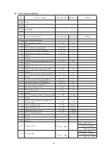
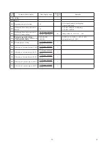
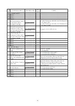
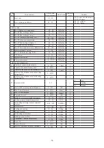
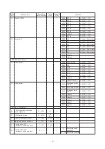
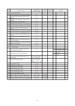
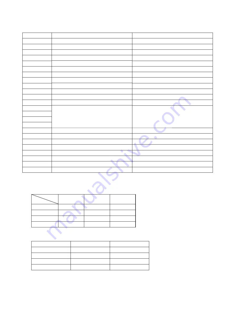
(2) Outdoor PCB setting
Code
Input
Remarks
SW1
Outdoor address No. (Order of 10)
SW2
Outdoor address No. (Order of 1)
SW3-1
Inspection LED reset
Normal
★
/Reseet
SW3-2
Automatic backup operation
None
★
/With
SW3-7
Forced heating/cooling
Normal
★
/Forced heating-cooling
SW3-8
Test mode
Normal
★
/Test
SW5-1
Test run SW
Normal
★
/Test run
SW5-2
Test run
Heating
★
/Cooling
SW5-3
Pump down SW
Normal
★
/Pump down
SW7
Data erase/Write
SW8
7-segment display code No. increasing (order of 1)
SW9
7-segment display code No. increasing (order of 10)
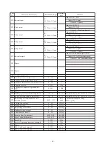
SW4-1
Model selection
See following table.
SW4-2
SW4-3
SW4-4
SW4-5
Demand ratio selection
See following table.
SW4-6
Demand ratio selection
See following table.
SW5-5
SL selection
New SL
★
/Previous SL
J11
Power supply voltage selection
Open
J12
Power supply voltage selection
Open
J13
External input Level/Pulse
Level
★
/Pulse
J14
Defrost reset temperature
Normal
★
/Intensive
J15
Defrost start temperature Normal/Cold region
Normal
★
/Cold weather region
Note (1) Jumper wires J13, J15 indicate short-circuit/open.
(2) Dip switch SW’s indicate OFF/ON.
(3)
★
indicates the factory default setting (OFF).
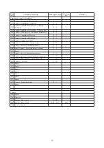
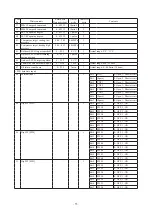
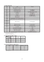
Model selection with SW4-1 – SW4-4
Model
Switch
FDC224
FDC280
FDC335
SW4-1
0
1
0
SW4-2
0
0
1
SW4-3
0
0
0
SW4-4
0
0
1
Note (1) 0: OFF, 1: ON
Demand ratio selection with SW4-5, SW4-6
SW4-5
SW4-6
Compressor capacity (%)
0
0
80
1
0
60
0
1
40
1
1
0
Note (1) 0: OFF, 1: ON
Summary of Contents for 112KXE6
Page 105: ... 101 Model FDC335KXE6 A PCB003Z035 shows local wining ...
Page 134: ... 130 PJF012D003 ...
Page 135: ... 131 ...
Page 139: ... 135 PJA012D751 b ...
Page 140: ... 136 ...
Page 206: ... 202 2 model type DIS model type HEAD ...
Page 207: ... 203 2 2 ...
Page 208: ... 204 2 2 2 2 2 ...


