–
126
–
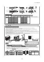
Signal line
CASE 1
CASE 2
CASE 3
CASE 4
Refrigerant pipe
Network connector
Network connector
Network connector
Network connector
Outdoor unit
Outdoor unit
Outdoor unit
Indoor unit
Indoor unit
Indoor unit
Indoor unit
Indoor unit
Indoor unit
Outdoor unit
Outdoor unit
Outdoor unit
Indoor unit
Indoor unit
Indoor unit
Indoor unit
Indoor unit
Indoor unit
Outdoor unit
Outdoor unit
Outdoor unit
Indoor unit
Indoor unit
Indoor unit
Indoor unit
Indoor unit
Indoor unit
Outdoor unit
Outdoor unit
Outdoor unit
Indoor unit
Indoor unit
Indoor unit
Indoor unit
Indoor unit
Indoor unit
OK
OK
※
1
×
※
2
OK
OK
OK
OK
×
×
OK
OK
OK
Case 1
Case 2
Communication protocol
new SL
previous SL
Address setting method
When only one refrigerant system is involved (signal
lines do not link with plural refrigerant systems)
Indoor unit address setting
000
-
127[47](*1)
000
000
00
-
31[47]
49
49
Indoor unit address setting
00
-
47
49
×
00
-
47
49
×
00
-
31[47]
49
00
~
31
Outdoor unit address setting
00
-
47
49
×
Outdoor unit address setting
0 1
2
3
4
5
6
7
8
9
0 1
2
3
4
5
6
7
8
9
●
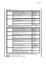
Address No. setting
Set SW1 through 4 and SW5-2 provided on the PCB and SW1 & 2 provided on the outdoor unit PCB as shown in the drawings below.
●
Address setting methods
The following address setting methods can be used. The procedure for automatic address setting is different from the conventional one.
Please use the automatic address setting function after reading this manual carefully.
※
1 Do not connect the signal line between outdoor units to A1 and B1. This may interrupt proper address setting. (Case 3)
Do not connect the signal line between indoor unit and outdoor unit to A2 and B2. This may interrupt proper address setting. (Case 4)
※
2 In Case 2, automatic address setting is not available. Set addresses manually.
A1・B1 A2・B2
A
B
A
B
A
B
A
B
A
B
A
B
A1・B1 A2・B2
A1・B1 A2・B2
A1・B1 A2・B2
A
B
A
B
A
B
A
B
A
B
A
B
A1・B1 A2・B2
A1・B1 A2・B2
A1・B1 A2・B2
A
B
A
B
A
B
A
B
A
B
A
B
A1・B1 A2・B2
A1・B1 A2・B2
A1・B1 A2・B2
A
B
A
B
A
B
A
B
A
B
A
B
A1・B1 A2・B2
A1・B1 A2・B2
×
×
●
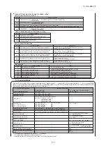
Summary of address setting methods (figures in [ ] should be used with previous SL)
(*1) Do not set numbers other than those shown in the table, or an error may be generated.
Note: When units supporting new SL are added to a network using previous SL such as one involving FD
○
A
△△
KXE4 series units, choose previous SL for the communication
protocol and set addresses manually.
●
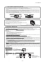
An outdoor unit No., which is used to identify which outdoor unit and indoor units are connected in a refrigerant system, is set on outdoor unit PCB and indoor unit PCB.
Give the same outdoor unit No. to all outdoor unit and indoor units connected in same refrigerant system.
●
An indoor unit No. is used to identify individual indoor units. Assign a unique number that is not assigned to any other indoor units on the network.
When plural refrigerant systems are linked with signal lines
(e.g., to implement central control)
Incorrect cable connection
(The signal line between outdoor units is connected to A1 and B1)
Incorrect cable connection
(The signal line between indoor unit and outdoor units is connected to A2 and B2)
Manual address setting
(previous SL/new SL)
Units supporting new SL
Units not supporting new SL
Automatic Manual
Automatic
Manual
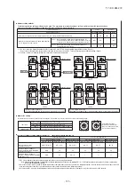
SW1 (SW3)
SW2 (SW4)
For ten’s place
For one’s place
By inserting a flat driver
(precision screw driver) into
this groove and turn the arrow
to point a desired number.
Indoor PCB
Outdoor PCB
SW1, 2 (blue)
SW3, 4 (green)
SW5-2
SW1, 2 (green)
For setting indoor No. (The ten’s and one’s)
For setting outdoor No. (The ten’s and one’s)
Indoor No. switch (The hundred’s Place) [OFF : 0, ON : 1]
For setting outdoor No. (The ten’s and one’s)
When signal lines linking plural refrigerant systems are
provided between outdoor units. (When the network connector
is disconnected, refrigerant systems are separated each other.)
When signal lines linking plural refrigerant systems are
provided between indoor units.
Automatic address setting for
multiple refrigerant systems installation
(with new SL only)
Automatic address setting for
single refrigerant system installation
(previous SL/new SL)
Indoor No. switch
Outdoor No. switch
Outdoor No. switch
Indoor No. switch
Outdoor No. switch
Outdoor No. switch
'17 • KX-SM-272
Summary of Contents for 140KXZEN1
Page 153: ... 17 KX SM 272 151 ...
Page 154: ... 17 KX SM 272 152 ...
Page 155: ... 17 KX SM 272 153 ...
Page 156: ... 17 KX SM 272 154 ...
Page 165: ... 163 MEMO 17 KX SM 272 ...

