background image

9

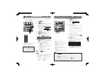
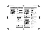
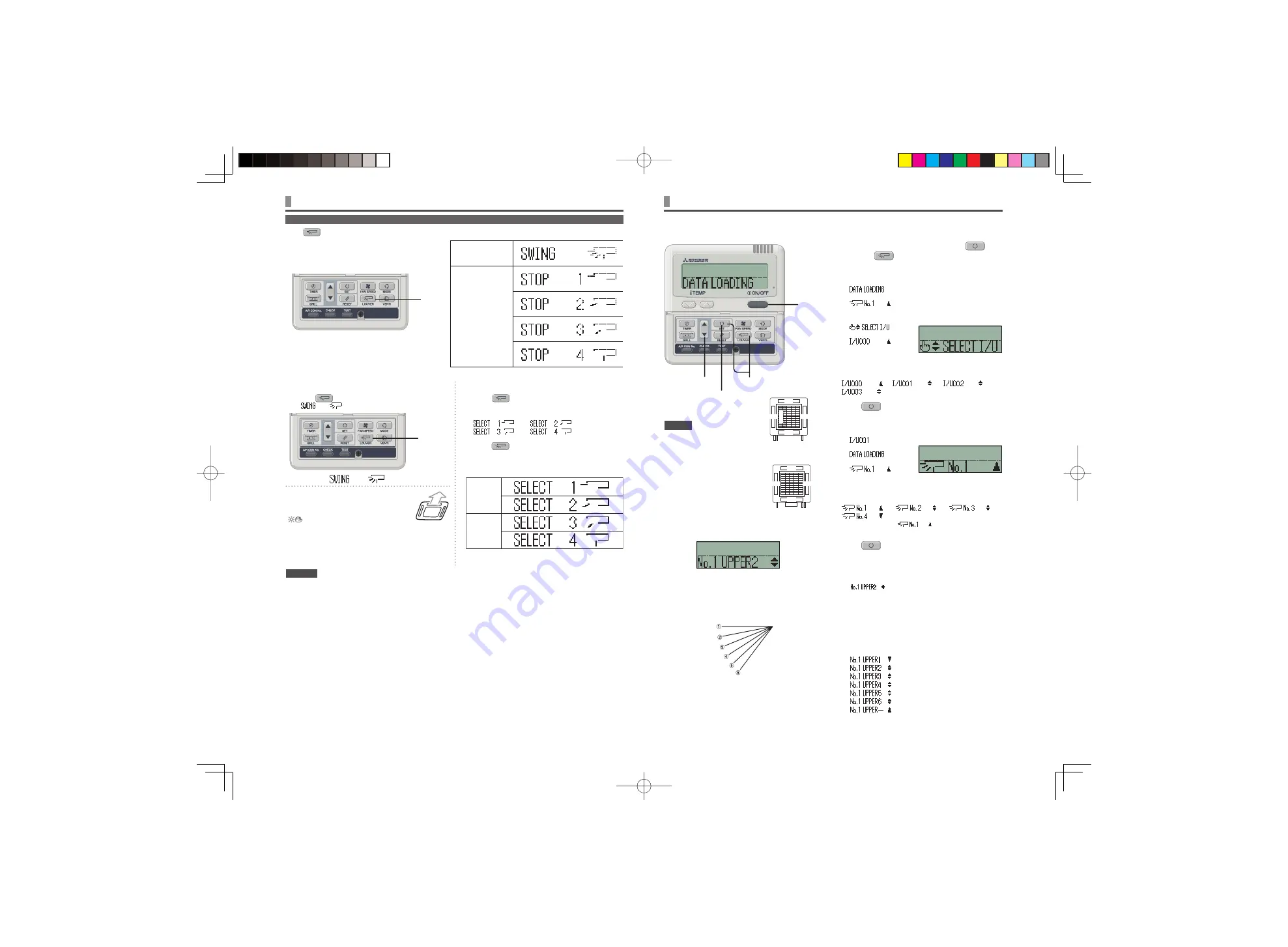
Press 

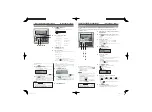
 LOUVER button once, and the current status of louver is displayed.

ADJUSTING WITH LOUVER BUTTON (Indoor unit with auto swing function)


HOW TO ADJUST THE LOUVER


< WIRED REMOTE CONTROL >

The display during 
auto swing

The display with the  
louver position fixed 

When you operate the swing louver

1.

  Press


 LOUVER button, and button the display to 


”.

The function of the swing louver 
during the heating preparation, 
heating/defrost

” or “Heating/Defrost” is 

displayed, the position of the swing louver is 
automatically switched to horizontal.

When the operation is switched to normal after “The heating 
preparation” or “Heating/Defrost” ends, the position of swing louver 
returns to that of setting.

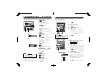
When the position of the swing louver is fixed

1.

 Press


 LOUVER button once while the louver 

is swinging, and 4 stop positions are displayed every 
one second in order.


2.

 Press


 LOUVER button once when the display 

of the louver comes to the position you desire.


The display is switched to stop, and the position of louver is fixed.

Recommended louver fixed position

COOL•DRY 

HEAT

horizontal position

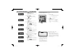
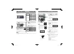
Stop the air conditioner and press 

 SET 

button and 

 LOUVER button simultaneously 

for three seconds or more.

The following is displayed if the number of the indoor units 
connected to the remote control is one. Go to step 

4

.

È

The following is displayed if the number of the indoor units 
connected to the remote control are more than one

È

Press 

 or 

 button.(selection of indoor unit)

Select the indoor unit of which the louver is set.

[EXAMPLE]

Press 

 SET button. (determination of 

indoor unit)

Selected indoor unit is fixed.

[EXAMPLE]

” (lit for two seconds)

È

È

Press 

 or 

 button. (selection of louver No.)

Select the louver No. to be set according to the left figure.

[EXAMPLE]

” 

⇔ 

” 

⇔ 

” 

⇔ 

Note :  For FDE, select “

”. Other louver No. settings 

have no effect.

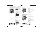
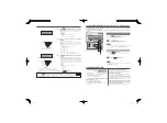
Press 

 SET button. (Determination of 

louver No.)

The louver No. to be set is confirmed and the display shows the 
upper limit of the movable range.

[EXAMPLE]  If No.1 louver is selected,

” 

current upper limit position

Press 

 or 

 button. (selection of upper limit 

position)

Select the upper limit of louver movable range.
“position 1” is the most horizontal, and “position 6” is the most 
downwards.
“position  --” is to return to the factory setting. If you need to 
change the setting to the factory setting, use “position --”. 

” (The most horizontal)

⇔ 

⇔ 

⇔ 

⇔ 

⇔ 

” (The most downward)

⇔ 

” (Return to the position of shipment)

2•4•6•8 1 

10 

3•5•7•9 


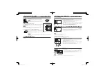
HOW TO SET THE AIRFLOW DIRECTION 

(IN CASE OF FDT, FDTC, FDE) <WIRED REMOTE CONTROL>

No. 4

No. 2

No. 1

No. 3

Control bo

x

Piping side

Drain hose side

Louver No.

[for FDT]

It is possible to change the movable range of the louver on the air outlet from the wired remote control. Once the top and bottom position is 
set, the louver will swing within the range between the top and the bottom when swing operation is chosen.
With Ceiling cassete −4 way − FDT and FDTC, it is also possible to apply different setting to each louver.

NOTICE

• 

For FDT and FDTC type, in case the 
louver No. to be set is uncertain, set 
any louver temporarily. The louver 
will swing once when the setting 
is completed and it is possible to 
confirm the louver No. and the 
position.
After that, choose the correct louver 
No. and set the top and bottom 
position.

• 

For FDE type, set louver No. 1. 
Other settings selected have no 
effect.

(downwards)

(horizontal)

the position of the louver

Press

Press

CAUTION 

• 

Do not move the swing louver forcibly by hands for fear that it may be damaged.

• 

Do not blow downwards during cooling operation for a long time for fear that dew condensation may be formed at the side panel. 

(In 

case of FDE)

No.2

No.1

No.3

No.4

Control box

Drain hose side

Piping side

Louver No.

[for FDTC]

PSA012B735_EN.indd   9

PSA012B735_EN.indd   9

2009-9-3   9:57:32

2009-9-3   9:57:32

Summary of Contents for AVANTI PLUS SRK25ZSXA-W

Page 1: ...ire cumple con la directiva EMC 2004 108 EC LV Directiva 2006 95 EC La indicación CE sólo corresponde al área de suministro eléctrico de 50 Hz Este aparelho de ar condicionado está em conformidade com a Directiva EMC 2004 108 EC a Directiva LV 2006 95 EC A marca CE aplica se à zona de fornecimento de energia a 50 Hz Το κλιματιστικό συμμορφώνεται προς την οδηγία 2004 108 ΕΚ περί ηλεκτρομαγνητικής σ...

Page 2: ...is mishandled Note however that depending on the situation the items listed in the CAUTION sections do also have the potential of causing serious outcomes Both warnings and cautions provide you important information related to safety please make sure to observe them The symbols used throughout the main text of this manual have the following meaning marks mean danger alarm and caution The specified...

Page 3: ...or checking indoor unit be sure to turn off Indoor unit power supply breaker It can result in electric shock or injury due to rotation of indoor unit fan if you perform check or repair with the Indoor unit power supply breaker turned on Place the panels removed for repairing or checking on the stable spot Otherwise dropping or falling may lead to injury CAUTION PRECAUTIONS FOR RELOCATION OR REPAIR...

Page 4: ... is not a malfunction In that case the operation of the button is prohibited When you start to operate for the first time after turning the power supply on the unit starts to operate as below You can change the setting as you like Central control Turned off Operation changeover With auto mode auto cooling Without auto mode cooling Set temperature 23 C Fan speed Louver position Horizontal ATTENTION...

Page 5: ... display If you press button while timer mode is operative timer mode is canceled and the display will return to the original display If you do not press any button for several minutes after entering the timer mode the timer mode ends and returns to the original display ATTENTION After certain period has elapsed the unit stops operating Sleep timer The unit stops operating at each setting time onc...

Page 6: ...h only ON timer or only OFF timer HOW TO PERFORM THE TIMER OPERATION WIRED REMOTE CONTROL 1 Press TIMER button 2 Press button for three times Æ Æ Æ 3 Press SET button EXAMPLE flashes lit 4 Press or button Set the preferred time to start the operation Set Hour If you press or button for a while Hour display is changed by one hour and stops when you stop pressing Set Minute If you press or button th...

Page 7: ...nd returns to the original display NOTICE HOW TO PERFORM THE TIMER OPERATION WIRED REMOTE CONTROL 5 Press SET button mark next to a number is switched to light or is displayed The settings so far are effective and the display changes as shown on the left 6 Press or button Press button and is displayed Press button and is displayed Select either of the above two Press the RESET button to return to ...

Page 8: ...day Setting HOW TO PERFORM THE TIMER OPERATION WIRED REMOTE CONTROL Weekly timer Holiday Setting It is possible to disable the timer settings temporarily which has been already set by applying Holiday Set on a particular day of the week When the Holiday Setting is cancelled the timer setting is enabled again 1 In the Weekly timer mode select and set See Selecting Weekly timer setting step 1 to 5 o...

Page 9: ...s SET button and silent setting is canceled ending the silent mode is displayed SILENT MODE Silent Mode Setting If you press button while silent mode is operative silent mode is canceled and the display will return to the original display Note that the setting which has not been completed is canceled HOW TO PERFORM THE TIMER OPERATION WIRED REMOTE CONTROL TIMER CACELLATION MODE 2 4 7 1 3 5 6 In ca...

Page 10: ...lect Other louver No settings have no effect 5 Press SET button Determination of louver No The louver No to be set is confirmed and the display shows the upper limit of the movable range EXAMPLE If No 1 louver is selected current upper limit position 6 Press or button selection of upper limit position Select the upper limit of louver movable range position 1 is the most horizontal and position 6 i...

Page 11: ...educed Moreover it leads to waste of electricity and larger operation noise It may cause failure Dew may form and drop during cooling Do not block the inlet and outlet grilles of the indoor and outdoor units Excessive load to the unit may cause failure Keep moderate room temperature Too much cooling or heating is not good for your health It will also waste the electricity Block direct sunlight and...

Page 12: ...onds when FILTER button is pressed OFF TIMER display Indicates when OFF TIMER is set See page 12 OPERATION MODE select button Every time this button is pressed displays switch as below AUTO COOL HEAT FAN DRY ROOM TEMP TIME SETTING button Sets room temperature by pressing or button Sets time when setting the time RESET switch Used to reset the microcomputer TIME SET UP switch Sets current time See ...

Page 13: ...r supply The crankcase heater is conducted while the compressor is stopped preventing failure of the compressor due to accumulation of liquid refrigerant by keeping the compressor warm The operation of remote control must be performed slowly and steadily HOW TO USE WIRELESS REMOTE CONTROL ATTENTION 4 1 5 3 2 AUTO COOL HEAT DRY FAN Guideline of room temperature setting COOL 26 to 28 C DRY 21 to 24 ...

Page 14: ...rror code symptom of the trouble air conditioner type and model name etc Press the ON OFF button to stay the air conditioner on the stop mode Light for 0 5 second wink out for 0 5 second Timer check indicator lamp WHEN LONG FLASHING LIGHT IS SHED FROM THE TIMER CHECK INDICATOR LAMP YELLOW Clean the filter See page 14 When cumulative running time reaches 120 hours long flashing light light for 2 se...

Page 15: ...ok on the grille E 2 places and push it securely until the filter is caught by the hook How to mount the grille 1 Hang the hook on the hole on the panel The hook on the grille can be hanged 3 sides on the panel 2 After the grille is hanged close the grille while the stopper on the grille 2 places is kept pressed to OPEN direction When the grille comes to the original position release the stopper t...

Page 16: ...started when the compressor is activated deactivated during operation or when the operation is stopped These are the sounds of the refrigerant flowing through the system Sounds of rustling or gurgling may be heard from a stopped indoor unit These sounds can be heard when the air conditioning system is performing automatic control The supply air from the indoor unit smells bad The supply air from t...

Page 17: ...place Are there any obstacles If so it leads to the decrease of the efficiency and the increase of operation noise Avoid the place where cool warm air and operation noise cause problems to your neighbors INSTALLATION LOCATION Normally the efficiency of the air conditioning system will become lower after a while because dirt accumulates inside the system This occurs gradually in around 3 years of u...

Reviews: