background image

1

Thank you very much for your purchase of this packaged air conditioning system produced 
by Mitsubishi Heavy Industries. Please read through this manual before using the 
product and use the product appropriately according to the instructions in the manual. 
After you have read the manual, store it with the warranty certifi cate in a safe place. 

This Product contains fl uorinated greenhouse gases.
Do not vent R32 into the atmosphere: R32 is a fl uorinated greenhouse gas with 
a Global Warming Potential (GWP) = 675.
Do not vent R410A into the atmosphere: R410A is a fl uorinated greenhouse gas 
with a Global Warming Potential (GWP) = 2088.
Refer to a label on outdoor unit for the weight of fl uorinated greenhouse gas and 
CO

2

 equivalent.

The emission sound pressure level from each Indoor and Outdoor unit is under 
70 dB(A).


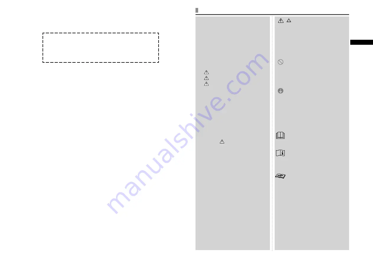
SAFETY PRECAUTIONS


J

Please read these 
“SAFETY PRECAUTIONS” 
before starting to use 
this product and use the 
product appropriately 
according to the 
instructions.


J

The precautions provided 
here are classified into 

 DANGER” and 

 CAUTION”. The 

 DANGER” sections 

describe potentially 
hazardous situations 
that may lead to serious 
outcomes such as death 
and serious injuries if the 
product is mishandled. 
Note, however, that 
depending on the 
situation, the items listed 
in the “

 CAUTION” 

sections do also have 
the potential of causing 
serious outcomes. Both 
warnings and cautions 
provide you important 
information related to 
safety ; please make sure 
to observe them.


J

The symbols used 
throughout the main text 
of this manual have the 
following meaning.

 marks mean danger, 

alarm, and caution. The 
specified prohibited 
item is described in the 
triangle. The left mark 
means “Shock hazard 
alarm”.

{

marks mean 

prohibited items. The 
specified prohibited 
item is described in the 
circle or in the vicinage.

z

 marks mean 

compulsory action 
or instruction. The 
specified prohibited 
item is described in 
the circle. The left 
mark means “Earth is 
needed”.
The user’s manual 
should be read 
carefully.
There is information 
included in the 
user’s manual and/or 
installation manual.
A service personnel 
should be handing 
this equipment with 
reference to the 
installation manual.


J

After you have read the 
manual, always store it 
where other users can 
refer to at any time. If a 
new owner takes over the 
system, make sure to pass 
this manual. 


J

SAFETY PRECAUTIONS

 ...................................................................................................................................................1


J

HOW TO  USE

< WIRED REMOTE CONTROL (RC-E series) >

NAMES AND FUNCTIONS OF REMOTE CONTROL BUTTONS ......................................................................................5

HOW TO OPERATE ............................................................................................................................................................5

HOW TO PERFORM THE TIMER OPERATION .................................................................................................................6

THE SELECTION OF TIMER MODE ...............................................................................................................................6

SETTING THE TIME.........................................................................................................................................................6

SLEEP TIMER MODE ......................................................................................................................................................7

OFF TIMER MODE ...........................................................................................................................................................7

ON TIMER MODE ............................................................................................................................................................7

WEEKLY TIMER MODE ...................................................................................................................................................8

TIMER CANCELLATION MODE ..................................................................................................................................... 10

HOW TO OPERATE IN SILENT MODE ............................................................................................................................ 11

HOW TO ADJUST THE LOUVER ..................................................................................................................................... 11

HOW TO SET THE AIR FLOW DIRECTION ..................................................................................................................... 12

AIROUTLET SELECTION ................................................................................................................................................ 12

HOW TO OPERATE VENTILATION .................................................................................................................................. 13

FOR COMFORTABLE USE .............................................................................................................................................. 13

INSPECTION DISPLAY, FILTER SIGN, AIR CONDITIONER NUMBER, STANDBY, ROOM TEMPERATURE AND 

BACK UP DISPLAY .......................................................................................................................................................... 13


J

TROUBLE SHOOTING

 ..................................................................................................................................................... 14


J

NOTICE

PREPARATION OF HEATING .......................................................................................................................................... 14

AUTO RESTART ............................................................................................................................................................... 14

SETTING TO DISABLE BUTTON OPERATION ............................................................................................................... 15

INSTALLATION, RELOCATION, AND INSPECTION MAINTENANCE ............................................................................. 15

OPERATION RANGE ....................................................................................................................................................... 15

MAINTENANCE AND INSPECTION GUIDELINE OF MAIN PARTS OF PACKAGED AIR CONDITIONER .................... 16

ENGLISH

Summary of Contents for FD Series

Page 1: ...αείναι50Hz FD series Inverter Packaged Air conditioners Ceiling cassette 4 way FDT Ceiling cassette 4 way Compact FDTC Duct connected High static pressure FDU Duct connected Middle static pressure FDUM Ceiling suspended FDE KX KXR VRF inverter multi system Air conditioners Ceiling cassette 4 way FDT Ceiling cassette 4 way Compact FDTC Ceiling cassette 2 way FDTW Ceiling cassette 1 way Compact FDTQ...

Page 2: ......

Page 3: ... the main text of this manual have the following meaning marks mean danger alarm and caution The specified prohibited item is described in the triangle The left mark means Shock hazard alarm marks mean prohibited items The specified prohibited item is described in the circle or in the vicinage zmarks mean compulsory action or instruction The specified prohibited item is described in the circle The...

Page 4: ...enance shall not be made by children without supervision This unit should be installed in rooms which exceed the floor space specified in installation sheets of indoor outdoor unit Refer to the installation sheet INSTALLATION PRECAUTIONS DANGER Make sure to have the installation done by your dealer or a specialist If you install by yourself and the unit is not properly installed water leakage elec...

Page 5: ...amaged and lead to water leakage If the detergent is dropped on the electric component or motor it may lead to failure smoking or ignition Do not place a burning appliance where the air flow from the unit is directly blown It may cause the imperfect combustion of the equipment Make sure that the unit installation foundation is not damaged due to long term use If it is left to stand the unit may fa...

Page 6: ... leakage or short circuit PRECAUTIONS FOR RELOCATION OR REPAIRING CAUTION Never perform any modification Contact your dealer for repairing Improper repairing may lead to water leakage electric shock or fire Normally the refrigerant does not leak But if it leaks and contacts fire such as fan heater space heater or cooking heater it may produce toxic chemicals When repairing refrigerant leakage dete...

Page 7: ...ners keep the power supply on for six hours before initial operation The crank case heater is energized in order to heat up the compressor Do not turn off the power supply Power is distributed to the crankcase heater even if the compressor is stopped This keeps the compressor warm and prevents failures caused by accumulation of liquid refrigerant Operation mode DRY COOL FAN HEAT AUTO The display o...

Page 8: ...time È The unit starts operating at the setting time È Timer set for each day of the week È Cancel the timer setting If you press the RESET button timer mode ends and return to original status 3 Press SET button The selected timer mode is set For setting of each timer mode see the following pages The possible combination of the timer function is mentioned in the following table Combination of mode...

Page 9: ...ring the timer mode the timer mode ends and the display returns to the original one NOTICE 1 Press TIMER button 2 Press ź button once Æ 3 Press SET button EXAMPLE flashes lights 4 Press Ÿ or ź button The display changes as below Set as you like 5 Press SET button Sleep timer has been set The air conditioner will turn on if a sleep timer is set while it is turned off After is displayed in the displ...

Page 10: ...isplay area 4 Press Ÿ or ź button By pressing Ÿ or ź button it is possible to choose the item to set for setting the timer Ľ for setting the selected day of the week to holiday Ľ for checking the timer setting and canceling individual settings 5 Press SET button The selected mode is fixed 3 5 2 4 1 JWEEKLY TIMER SETTING 1 In the Weekly timer mode select and press SET button to confirm See step 1 t...

Page 11: ...isplay is turned off and the following is displayed lights lights for two seconds È lights lights After the holiday setting has been completed the display of the remote control returns to that of step 1 Repeat step 2 and 3 to continue canceling further holiday settings 4 Press button Timer mode ends If you press button while timer mode is under setting timer mode is canceled and the display will r...

Page 12: ...isplay returns to the original one NOTICE JWeekly timer Checking 1 In the Weekly timer mode select and set See Selection of Weekly timer mode step 1 to 5 on page 8 The display shows the detailed timer operation setting information of the smallest timer operation number on the day of the week as shown on the left But if not set is displayed 2 Press Ÿ or ź button Detailed timer operation settings ar...

Page 13: ...utton The following setting is displayed flashing lights 5 Press Ÿ or ź button Set the ON TIME Set Hour If you hold Ÿ or ź the number in Hour display changes and if you release it the number stops changing Set Minute If you press Ÿ or ź button the number in the display becomes larger or smaller by ten minutes If you press the RESET button the remote control return to the display 6 Press SET button...

Page 14: ...selecting to upper air flow Set the upper and lower limit position to UPPER 2 and LOWER 2 No 1 UPPER 2 LOWER 2 2 In case of selecting to upper and lower air flow Set the upper and lower limit position to UPPER 5 and LOWER 5 No 1 UPPER 5 LOWER 5 1 Stop the air conditioner and press SET button and LOUVER button simultaneously for three seconds or more The following is displayed if the number of the ...

Page 15: ...ning 1 Press RESET button The cumulative operation hours are reset and the FILTER CLEANING message turns off 1 ROOM TEMPERATURE DISPLAY If room temperature display setting is activated room temperature is displayed on the remote control display Then air flow display turns off but air flow adjusting button is operative Consult your dealer for settings Ç The room temperature display BACK UP DISPLAY ...

Page 16: ...ote control it is not possible to operate by the remote control Even if the wired remote control is operated central control light only flashes and doesn t operate Is not central controlling or center displayed If controlled with a separately purchased center console etc the unit cannot be operated by the remote control TROUBLE SHOOTING Check the following items before requiring service THE UNIT D...

Page 17: ... of lightning conductors and telephones If the ground work is not good it may lead to electric shock Caution A leakage breaker is necessary depending on the installation environment If it is not mounted there it may lead to electric shock Only qualified specialists of electrical and grounding work can do these works according to electric equipment technical standards Is the wiring designated for t...

Page 18: ...rmal sound generation The resistance value should be 1 MΩ or more When a bearing sound is loud replace the bearing Whentheresistancevalueis1MΩorless replacethe motor 20 000 Hr S Bearing Regular lubrication is required Audible inspection There should be no abnormal sound generation Replace parts regularly 15 000 Hr Consumable components Automatic louver motor Insulation resistance abnormal sound ge...

Page 19: ...etected 5 years z z z z z Cleaning object item Due to atmospheric dirt Piping in the unit Sympathetic vibration contact and corrosion of the piping in the unit Sympathetic vibration and contact of capillary tube Visual inspection Visual inspection There should be no abnormal sympathetic vibration sound or corrosion There should be no abnormal sympathetic vibration or contact wear Replace it or rea...

Page 20: ...no deposited foreign matter Retighten it if it is loose Cleanwithabrushincaseofdepositedforeignmatter adhesion 25 000 Hr S Electrical component including boards etc HIC board short circuit check Visual check of dirt adhesion to the board etc Self diagnosis mode appearance check Tester Visual inspection Visual inspection Should be of a specified resistance value There should be no deposited foreign...

Page 21: ...gory FDE Series FDFW Series FDK Series FDT Series FDTC Series FDTQ Series FDTS Series FDTW Series FDU Series FDUH Series FDUM Series FDUT Series FDU F Series DRED This air conditioner complies with DRED standards as per AS NZS4755 3 1 It supports demand response modes 1 2 and 3 DRM1 2 and 3 The outdoor unit of this air conditioner is equipped with a DRED specific terminal block It also supports EL...

Page 22: ...6TXDUH 6WRFNOH 3DUN 8 EULGJH 0LGGOHVH 8 7 8QLWHG LQJGRP 7HO D KWWS ZZZ PKLDH FRP MITSUBISHI HEAVY INDUSTRIES AIR CONDITIONERS AUSTRALIA PTY LTD RPPHUFLDO 5RDG LQJVJURYH 16 32 2 LQJVJURYH 16 7HO D KWWS ZZZ PKLDD FRP DX MITSUBISHI HEAVY INDUSTRIES MAHAJAK AIR CONDITIONERS CO LTD 6RL KDORQJNUXQJ ZDQJ DPSODWLHZ KHW DG UDEDQJ DQJNRN 7KDLODQG 7HO D KWWS ZZZ PDFR FR WK ...

Reviews: