background image

-


22


-

W

CNI

F2

T8

CN

CNQ

CNE

CNI3

CNW

CNI2

CNV1

CNM

F3

T1

T5

T4

T2

F1

CNL

CNTR

SW6

SW7

T7

T6

V

U

Outdoor air temp. thermistor,
Outdoor heat exchanger themistor,
Discharge pipe thermistor
(Tho-A, Tho-R, Tho-D)

DIP switch

(SW7)

Fan motor

Reactor

Stepping motor

Power transistor thermistor

(Tho-IPM)

DIP switch

(SW6)

Sub PCB

(Noise filter)

Function of DIP switches (SW5) (Usually all turned OFF)

Defrost Setting Select For cold regions.
Normal

Low refrigerant protection control-Effective
Low refrigerant protection control-Invalid
Test run operation-Heating
Test run operation-Cooling

SW5-1

SW5-2

SW5-3

SW5-4

ON

OFF

ON

OFF

ON

OFF

ON

OFF

Snow-guard fan control-Effective
Snow-guard fan control-Invalid

Switch

Function

Change by the jumper wire

SW5

SW5

SW9

Test run operation switch

1

2

3

4

SW9

CNQ1

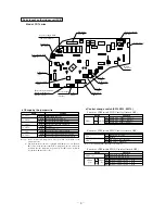
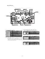
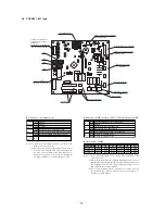
  Parts layout on the outdoor unit PCB

S

FDCVA151~251 type

151

201

251

Model

None
None

With

None

With

None
None
None
None

With

None
None
None

With
With

JA1 (SW7-1)
JA5 (SW6-1)
JA6 (SW6-2)
JA7 (SW6-3)
JA8 (SW6-4)

Notes (1) “None” means that jumper wire is not provided on the PCB or the connection is cut

Notes

 (2) The replacement PCB is not equipped with jumper wires JA1 and JA5~JA8. Instead, SW6 and 7

are mounted in the same position and have the same functions as jumper wires JA1 and JA5~JA8.

Carry out the local settings in accordance with the table using SW6 and 7.

Note (1) “None” means that jumper wire is not provided on the 

PCB or the connection is cut.

Model selection-Energy saving
Model selection-Standerd

JA3

(SW7-3)

with

None

Switch

Function

Change by the JA3

External PCB

Summary of Contents for FDA Series

Page 1: ...S SE ER RV VI IC CE E M MA AN NU UA AL L F FD DA A S Se er ri ie es s S Sp pl li it t S Sy ys st te em ms s F FD DA A S Se er ri ie es s M Mu ul lt ti i S Sy ys st te em ms s ...

Page 2: ......

Page 3: ...ATA 2 ERROR CODES 4 PCB INDOOR UNITS 8 ERROR DISPLAY REMEDY CHART 12 PCB OUTDOOR UNITS 22 ERROR DISPLAY OUTDOOR UNIT 25 OPERATIONAL DATA CHECK WIRED CONTROLLER 35 REMOTE CONTROL WIRED 36 SETTING FUNCTIONS 37 ERROR DISPLAY WIRELESS CONTROL 43 REMOTE CONTROL WIRELESS 44 ...

Page 4: ...essure to expel air Notes 2 Do not use the compressor for evacuation Notes 3 Do not operate the compressor in a vacuum condition Vacuuming begins Vacuuming completed Vacuum gauge check When the vacuum gauge s needle pointer creeps up there is moisture left in the system or a leak Pull air again after you have checked the system for a leak and rectified it Use a reverse flow stop adapter to prevent...

Page 5: ...ting condition by operation pressure and temperature difference Making an accurate judgement requires a skill that is acquired only after years of experience one trouble may lead to an another trouble from a single trouble source and several other troubles may exist at the same time which comes from a undetected different trouble source Filtering out the trouble sources can be done easier by compa...

Page 6: ...shes continuously or is off E1 E5 E6 E7 E9 E10 E28 Cause Keeps flashing Keeps flashing 1 time flash Stays OFF E8 Stays OFF Stays OFF Stays OFF Power OFF L phase wiring is open power source failure Stays OFF Remote controller wires X and Y are reversely connected For wire breaking at power ON the LED is OFF Remote controller wire is open X wire breaking A beep is produced and no indication is made ...

Page 7: ... type DC fan motor abnormal FDCVA 151 251 type Remote controller error code E32 E33 E34 E36 E37 E38 E39 E40 E47 E48 Cause Keeps flashing Keeps flashing Stays OFF 1 time flash E35 Keeps flashing Stays OFF 1 time flash Current Abnormalities in a compressor over current E42 Keeps flashing Keeps flashing Stays OFF Lights contiously 52C abnormal FDCA 301 601 type E52 Keeps flashing Keeps flashing Stays...

Page 8: ...n limit when multiple units are control by a single remote controller Broken wire of indoor unit return air thermistor Error detail Error code Timing of error detection Broken wire of heat exchanger thermister Broken wire of discharge pipe thermistor Broken wire of outdoor air temperature thermistor Broken wire of power transistor thermistor When a thermistor input temperature of 30 C or lower is ...

Page 9: ...the ON OFF button on the remote controller Or disconnect and reconnect the power supply connector CNW1 or CNW0 on the indoor unit control PCB or turn the main power supply OFF Turn the main power supply OFF 3 Error diagnosis procedures at the indoor unit side To diagnose the error measure the voltage AC DC resistance etc at each connector around the circuit board of indoor unit based on the inspec...

Page 10: ...J1 SW7 1 J2 SW7 2 J3 SW7 3 J4 SW7 4 J5 SW8 1 J6 SW8 2 With None 1 With None 1 With None 1 With None 1 With None 1 With None 1 Name Function Note 1 2 None means that jumper wire is not provided on the PCB or the connection is cut The replacement board is not equipped with jumpers J1 J6 Instead SW7 and 8 with the same functions as jumpers J1 J6 are used in the position where the jumpers were previou...

Page 11: ...ith None 1 Name Function Note 1 2 None means that jumper wire is not provided on the PCB or the connection is cut The replacement board is not equipped with jumpers J1 J6 Instead SW7 and 8 with the same functions as jumpers J1 J6 are used in the position where the jumpers were previously Set SW7 and 8 locally in accordance with the above table Setting time 1000hrs Unit stop Setting time 1000hrs Di...

Page 12: ...ne 1 With None 1 With None 1 With None 1 Name Function Note 1 2 None means that jumper wire is not provided on the PCB or the connection is cut The replacement board is not equipped with jumpers J1 J8 Instead SW7 and 8 with the same functions as jumpers J1 J8 are used in the position where the jumpers were previously Set SW7 and 8 locally in accordance with the above table Setting time 1000hrs Uni...

Page 13: ...ith None 1 Name Function Note 1 2 None means that jumper wire is not provided on the PCB or the connection is cut The replacement board is not equipped with jumpers J1 J4 J6 Instead SW7 and 8 with the same functions as jumpers J1 J4 J6 are used in the position where the jumpers were previously Set SW7 and 8 locally in accordance with the above table Setting time 1000hrs Unit stop Setting time 1000...

Page 14: ... reset Notes 1 In models other than FDT replace the fuse 2 FDT only Note 1 In models other than FDT it is CNW2 Note 1 3 is GND Control lines connected wrong or disconnected Outdoor unit check Fuse exchange Transformer exchange Harness disconnection Unit is normal Malfunction was due to noise etc Replacement indoor unit power supply PCB Replacement indoor unit power supply PCB Replacement indoor un...

Page 15: ... 1 Power supply reset Maltifunction by accidental noise YES Normal NO YES Remote controller wire short circuit Remote controller defective Remote controller wire disconnection Remote controller defective NO Remeasure between X Z 10 11V YES YES Is the voltage between CNW8 1 3 12V NO Replacement indoor unit power supply PCB Replacement indoor unit control PCB NG Check the CNW5 8 harness OK Only case...

Page 16: ...3 of the outdoor unit s terminal block Measure the voltage between 2 N and 3 of the outdoor unit s terminal block Measure the voltage between 2 N and 3 of the indoor unit s terminal block Power supply fuse exchange Noise filter exchange Indoor unit control PCB defect Indoor outdoor unit control PCB defect Remote controller defect Remote controller wire disconnection Y Indoor unit control PCB defec...

Page 17: ...nt remote controller NO YES Replacement indoor unit control PCB Remote controller wire short circuit YES NO Replacement remote controller Noise Power supply reset Power supply OFF Remote controller wire is removed YES Indoor unit Red LED Green LED Stays OFF Stays OFF or Lights continuously Stays OFF Keeps flashing Red LED Green LED Outdoor unit YES NO YES YES NO NO NO YES Power supply reset Check ...

Page 18: ... unit heat exchanger thermistor Replacement YES YES NO NO Is the return air thermistor connector connection OK Correction Is the return air thermistor characteristics OK or is there a broken wire Defective return air thermistor Replacement Defective indoor unit control PCB Replacement Defective return air thermistor input circuit Note 1 Characteristics as per the above graph Display condition If a...

Page 19: ...the indoor heat exchanger thermistor OK Does the heating overload state exist NO YES NO NO YES Notes 1 Check if the overload state exists or not using the following check points Is there a short circuit Is the indoor heat exchanger dirty or clogged Is the outdoor unit s fan control normal Is the indoor or outdoor air temperature too high 2 See the figure page 142 for indoor heat exchanger thermist...

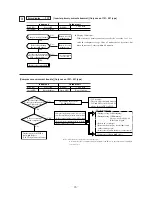
Page 20: ...thly by hand Is the voltage at CNM2 3 DC 1V or higher CNM1 1 and 3 Red White DC280V CNW9 1 and 3 DC15V Replacement indoor unit power supply PCB Replacement indoor unit control PCB Replacement indoor unit control PCB Detective fan motor Replacement indoor unit control PCB Replacement transformer Note 1 CNW9 3 is GND White is GND 3 is GND 1 2 Note 2 CNW9 3 is GND 9 Error display e16 Indoor unit Red ...

Page 21: ...n indoor unit fan motor s speed is detected to be less than 200 rpm continuously for 30 seconds the fan motor stops for 2 seconds After 2 seconds it starts again but this occurs 4 times within a period of 1 hour NO After check reset fan runs on Me Turn the power off and wait a short time 30 min 1 hr Check the circumstances Replacement fan motor Check the circumstances YES YES NO NO YES Was it repr...

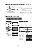
Page 22: ...or is there any broken wire Is the remote controller thermistor connector co nnection OK Correction Temperrature C 0 1 2 4 6 8 10 12 Resistance value kΩ 65 62 59 53 48 44 40 36 Temperrature C 14 16 18 20 22 24 26 28 Temperrature C 30 32 34 36 38 40 42 44 Temperrature C 46 48 50 52 54 56 58 60 Resistance value kΩ 33 30 27 25 23 21 19 18 Resistance value kΩ 16 15 14 13 12 11 9 9 9 2 Resistance value...

Page 23: ...rd can replaced with following procedure 1 Confirm the parts numbers Refer to the following parts layout drawing for the location of parts number Applicable Model FDCVA151HEN 201HEN 251HEN FDCA301HEN 401HEN FDCA301HES 401HES 501HES 601HES PCA505A080Z PCA505A065ZN PCA505A065ZS Parts No 1 2 3 4 5 6 ON 1 2 3 4 5 6 ON 1 2 3 4 5 6 ON 1 2 3 4 5 6 ON 1 2 3 4 5 6 ON 1 2 3 4 5 6 ON 17 27 10 Switch Setting ...

Page 24: ...ol Invalid Switch Function Change by the jumper wire SW5 SW5 SW9 Test run operation switch 1 2 3 4 SW9 CNQ1 Parts layout on the outdoor unit PCB S FDCVA151 251 type 151 201 251 Model None None With None With None None None None With None None None With With JA1 SW7 1 JA5 SW6 1 JA6 SW6 2 JA7 SW6 3 JA8 SW6 4 Notes 1 None means that jumper wire is not provided on the PCB or the connection is cut Note...

Page 25: ...rigerant protection control Effective Low refrigerant protection control Invalid Test run operation Heating Test run operation Cooling SW5 1 SW5 2 SW5 3 SW5 4 ON OFF ON OFF ON OFF ON OFF Snow guard fan control Effective Snow guard fan control Invalid Switch Function Notes 1 None means that jumper wire is not provided on the PCB or the connection is cut Notes 2 The replacement board is not equipped...

Page 26: ...s there a short cir cuit open circuit or dam age See 160 page for the check procedure DC Reactor Continuity Check 50 mΩ or higher less than 100 mΩ Fuse Check There should be continuity If faulty replace the control PCB When the outdoor unit fan motor is abnormal Refer to page 157 Noise Filter Check There should be continuity There should be no shorts between phases LED1 Red Check Light continuousl...

Page 27: ...ower supply Did it return to normal YES NO Outdoor unit s control PCB is faulty Network communications circuit is faulty Replace Malfunction is due to noise etc The outdoor unit s CPU went out of control due to noise during power on Indoor unit Red LED Green LED 2 time flash Keeps flashing Red LED Green LED Stays OFF Keeps flashing Outdoor unit 2 Error display e32 Power supply phases reversed Only...

Page 28: ...he voltage AC220 240V between the L1 and L3 phases and between the L2 and L3 phases on the 52C secondary side Is there overcurrent at the compressor Out of phase between the L1 and L2 phases Check the unit side Compressor is faulty Replace 52C is faulty There is a disconnection between 52C and CM or in the L1 and L2 phases between TB1 and 52C During cooling Is FMo turning During heating Is FMI tur...

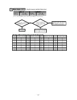
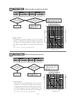
Page 29: ...surement correct NO A 58 5 53 5 48 5 58 B 53 5 48 5 43 5 53 48 65 1 Abnormal Temperature Detection Compressor speed rps Indoor heat exchanger temprature C less than 88 88 to less than 108 108 or higher 65 or more 60 or more 55 or more Is there a short circuit in the outdoor unit Is the installation space proper Is the refrigerant level too high Is the heat exchanger dirty or clogged 1 The compress...

Page 30: ...th liquid gas fully opened during both cooling and heating Is the installation space of indoor outdoor unit adequate Is there any short circuit air flow for indoor outdoor units If the discharge pipe temperature exceeds the set value the compressor s speed 151 251 or the expansion valve s opening angle 301 601 is controlled to prevent the discharge pipe temperature from rising The compressor s cap...

Page 31: ...20 80 100 120 Is the discharge pipe thermistor connector connection OK NO YES Repair Are the discharge pipe thermistor characteristics OK is there no broken wire Defective discharge pipe thermistor Replacement NO YES Defective outdoor unit control PCB Replacement Defective discharge pipe thermistor input circuit Temperature resistance characteristics of discharge pipe thermistor ThO D Thermistor r...

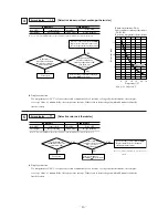
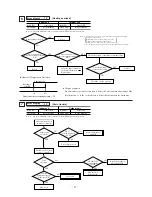
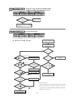
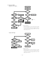
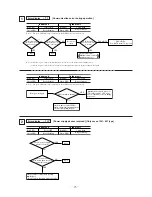
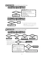
Page 32: ...an motor running Is there a short circuit in the outdoor unit Is there enough space for inlet and outlet 2 During Heating Is the indoor unit heat exchanger thermistor separated from the sensing case Is the filter clogged 3 During Cooling and Heating Is the refrigerant overcharge Is the service valve fully open While the 63H1 is operating 10 63H1 operation Only case of 301 601 type Indoor unit Red ...

Page 33: ...fan motor Is there foreign matter such as dust or dirt on the soldered surfaces of the control PCB NO YES Remove the foreign mater such as dust or dirt Is fuse F3 250V 1A blown NO YES Replace the fuse Replace the outdoor unit control PCB 13 DC Fan motor abnormal Only case of 151 251 type Indoor unit Red LED Green LED Stays OFF Keeps flashing Red LED 1 time flash Outdoor unit Error display e48 Disp...

Page 34: ...y the compressor restarts If this state is de tected 3 times in 40 minutes 16 Insufficient refrigerant volume Indoor unit Red LED Green LED Stays OFF Keeps flashing Red LED Green LED 1 time flash Keeps flashing Outdoor unit Error display e57 Is the service valve opened fully Are the connections of the connectors to the indoor heat exchanger and return air thermistor OK Are the characteristics of t...

Page 35: ...or 3 times the liquid re frigerant inside the compressor may be expelled from the compressor may recover from its starting abnormality NO E59 It does It does It doesn t It doesn t E59 diagnosis E42 diagnosis Compressor check It doesn t recur E60 recurs Does the compressor make any abnormal noise Does it return to normal when the power is reset Does E42 occur Again Operation Does the compressor sta...

Page 36: ...pt during acceleration or deceleration Power transistor module including drive circuit check method 1 Power transistor module terminal short circuit check procedure Disconnect the compressor wiring then conduct a short circuit check P U P V P W N U N V N W Check between the P N terminals Bring the tester probes in contact with the following places on each terminal P Power transistor P terminal U E...

Page 37: ...DING This message flashes while data are being read E8 ERROR DATA The data are then displayed beginning with item No 01 Displayed items are as shown below 7 Display the other data for when the error occurred in order from the currently displayed operation data No 01 using the or button Depending on the model items for which corresponding data do not exist are not displayed 8 To change the indoor u...

Page 38: ...lashing in red FAN SPEED switch This switch is used to set the airflow volume SET switch This switch is used to apply the timer operation setting This switch is also used to make silent mode operation settings RESET switch Press this switch while making settings to go back to the previous operation This switch is also used to reset the FILTER CLEANING message display Press this switch after cleani...

Page 39: ...t fan speed setting ON OFF Louver control setting ON OFF ON OFF 01 03 04 05 06 07 08 09 10 Function number A Factory setting Hi CEILING SET FILTER SIGN SET POSITION EXTERNAL INPUT SET ROOM TEMP OFF SET FAN CONTROL FREEZE PREVENT TEMP FREEZE PREVENT CONTROL Heating room temperature off set Heating fan control Louver control setting STANDARD Mild mode Hi CEILING 1 Powerful mode NO DISPLAY AFTER 180H...

Page 40: ... be displayed one by one Select a desired function 3 Press the SET button The screen display will be switched as follows SETTING Setting C ex AUTO RUN ON 4 Press either or button A list of Settings C will be displayed one by one Select your desired setting 5 Press the SET button The selected setting is displayed for 2 seconds then followed by SET COMPLETE and the function setting process is com pl...

Page 41: ...ion setting process is completed Then the screen display will be switched to Function number A Function description B so if you want to continue to set another function repeat the stepa as explained above To finish the function setting process please proceed to Step 8 8 Press AIR CON No button The screen display will go back to the indoor unit selection screen ex I U No 00 If you want to continue ...

Page 42: ...T b Press the button once The display will change to TEMP RANGE c Press the SET button to enter the temperature range setting mode d Using the or button select Hi LIMIT SET or Lo LIMIT SET the press the SET button e If Hi LIMIT SET is selected 1 The display changes from SET UP Hi LIMIT 22ºC flashing 2 Using the button select the upper limit value Display example Hi LIMIT 22ºC flashing 3 Press the ...

Page 43: ...No changes from flashing to lighted up continuously The message DATA LOADING is displayed flashing while data are being read OPERATION DATA and data No 01 are displayed 5 Display the other data in order from the currently displayed operation data No 01 by using the or button The items displayed are as shown at right Note 1 Depending on the model items for which corresponding data do not exist are ...

Page 44: ... Note 1 Items in show for the FDCA 301 601 b Checking the state of the unit in operation Check discharge pressure and suction pressure using the check joint provided inside the outdoor unit and the gas charge valve charge port The check joint in the unit is provided on the pipe connecting the four way valva and the heat exchanger and these points offer different pressure measurements depending on ...

Page 45: ...ollowing two kinds are displayed Lights contimously Under air conditioner operation Keeps flashing Under heating preparation Flashes 3 times when a signal is received from the remote controller Timer Check display Yellow The following three kinds are displayed Lights contimously Under timer operation Long lighting 2 second lighting 1 second stays OFF Filter sign Clean the air filter when this disp...

Page 46: ...ir flow direction button Used to start or stop the swing louver Signal sender Signals are sent to the air conditioner from here Filter reset indicator The FILTER mark is indicated when the FILTER RESET button is pressed Temperature indicator Set temperature is indicated Timer OFF time Indicated the timer OFF time When the timer mode is CONT or OFF there is no indication ON OFF button When the butt...

Page 47: ......

Page 48: ...g contract An installation guide is provided with the air conditioning equipment CE These Air Conditioners comply with EMC Directive 89 336 EEC LV Directive 73 23 EEC 3D Air Sales Ltd Sales Marketing Office 840 Brighton Road Purley Surrey CR8 2BH Telephone 020 8668 1112 Facsimile 020 8668 1113 3D Air Sales Ltd Technical Sales Admin Spares Warranty Anglia House Priors Way Coggeshall Essex CO6 1TL T...

Reviews: