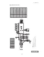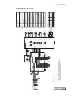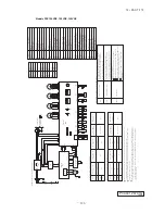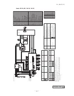
-
117
-
'12 • PAC-T-173
Capacitor for FMI
FS
CF
FMI
Transformer
Trl
SW2
Connector
CNB
Z
Drain motor
DM
TB1
Closed-end connector
Relay for FM
X1
ޓ
3,6
SW6
Operation check, Drain motor test run
SW7-1
Fuse
F
Thl -R1,2,3
Thl -A
Thc
LED
3
LED
2
Relay for DM
X4
TB2
ع
mark
Fan motor
㧔
with thermostat
㧕
Float switch
Indication lamp
㧔
Green-Normal operation
㧕
Indication lamp
㧔
Red-Inspection
㧕
Remote controller communication address
Model capacity setting
Terminal block
ާ
Power source
㧕㧔غ
mark
㧕
Terminal block
ާ
Signal line
㧕㧔غ
mark
㧕
Thermistor
ާ
Remote controller
㧕
Thermistor
ާ
Return air
㧕
Thermistor
ާ
Heat exchanger
㧕
XR5
㧔
Remote operation input:
Option
㧔
Operation
㧕
㧔
Heating
㧕
㧔
Compressor ON
㧕
㧔
Inspection
㧕
volt-free contact
㧕
Color
Mark
BK
Color Marks
Black
BL
Blue
BR
Brown
GR
Gray
OR
Orange
Color
Mark
RD
Red
WH
White
Y
Yellow
Y
㧛
GN
Yellow
㧛
Green
Earth
Power source line
Signal line
12
3
indoor unit and outdoor unit
Connecting line between
P
Pink
3
1
1
M
Thc
Y
Y
X
X
1
M
2
TB1
WH
CNW0
RD
CNB
CNM3
TB2
CNI
RD
RD
FS
CNN
Thl -R2
Thl -R1
FMI
CF
I
ޓ
RD
BK
WH
BL
CNW2
CNW1
Control PCB
Thl -A
CNH
LED
3
LED
2
SW2
SW7
SW6
F
㧔
3.15A
㧕
BL
WH
BK
BK
Y
12
3
4
3
1
WH
BK
WH
X6
X1
X2
X3
WH
19
7
35
CL
M
UH
H
RD
5
3
1
BK
BK
RD
BK
BK
t˚
F
㧔
3.15A
㧕
DM
BL
CNR2
3
1
F
㧔
0.16A
㧕
Y
㧛
GN
Thl -R3
56
GR
GR
BK
BK
BK
BK
12
RD
BR
BR
Y
㧛
GN
OR
Y
t˚
t˚
t˚
t˚
X4
CNR
WH
BR
WH
XR1
XR2
XR3
XR4
1
2
3
4
5
6
+12
CNT
BL
Y
Y
BL
WH
RD
WH
I
BR
Notes 1. indicates wiring on site
.
ޓޓ
2. See the wiring diagram of outside unit about the line between
ޓޓ
3. Use twin core cable
㧔
0.3mm X2
㧕
at remote controller line. See spec
ޓޓ
sheet of remote controller in case that the total length is more than 100m
.
ޓޓ
4. Do not
put remote controller line alon
gside
power source line.
inside unit and outside unit.
2
BL
19V
220
㨺
240V
Controller
24V
Remote
Trl
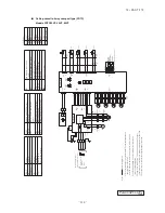
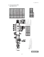
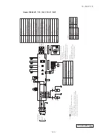
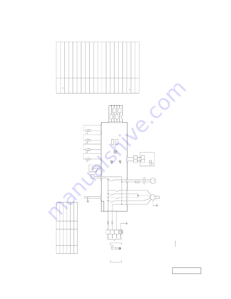
(d) Duct connected-High static pressure type (FDU)
Model FDU71VD
PJD001Z304
Summary of Contents for FDC Series
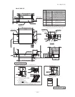
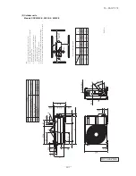
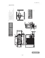
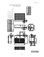
Page 95: ... 94 12 PAC T 173 Models FDT100VF 125VF 140VF H H H H H C B A F G D G PJF000Z285 ...
Page 98: ... 97 12 PAC T 173 Models FDEN60VF 71VF C 2 C 1 A B A B D C 1 C 2 C 1 C 2 E G F B PFA003Z817 ...
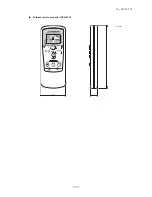
Page 113: ... 112 12 PAC T 173 b Wireless remote controller RCN E1R 60 17 150 Unit mm ...
Page 278: ... 277 12 PAC T 173 ー K ...
Page 346: ... 345 12 PAC T 173 Power PCB 1BSU OVNCFS 4GRNCEG VJG 2 ...
Page 518: ... 517 12 PAC T 173 3 5 SUPER LINK E BOARD SC ADNA E F SL2NA E and SL3N AE BE to control ...
Page 519: ... 518 12 PAC T 173 ...

