-
218
-
'12 • PAC-T-173
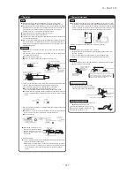
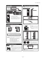
Work procedure
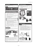
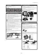
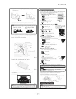
1. Select the suspension bolt locations and the pipe hole location.
(1) Use enclosed paper pattern as a reference, and
drill the holes for the suspension bolts and pipe.
̪
Decide the locations based on direct measurements.
(2) Once the locations are properly placed, the paper
pattern can be removed.
2. Install the suspension bolts in place.
3. Fix with 4 suspension bolts, which can endure load of 500N.
4. Check the measurements given at the right
figure for the length of the suspension bolts.
Paper pattern
Ceiling
Suspension bolt
Bracket
Pipe
Remove
Cut
25 mm or mor
e
45 mm or less
Hanging plate
Air supply
<
When installed against a ceiling material,
>
̪
Please fasten firmly with double nuts.
Hanging plate
Unit
Suspension bolt
Ceiling surface
Washer
(accessory)
̪
Double nuts
<
No ceiling material to install against,
>
Hanging plate
Unit
Suspension bolt
Nut
Washer
(accessory)
̪
Double nuts
Fasten
at the
front
end of
an
elon-
gated
hole.
Hanging plate
Screw for
hanging
plate (M4)
Fixing bolts
(M8)
0~3mm
0~3mm
(For left-side drain
connection, give the
reverse slope.)
Drain
socket
Heat insulation material
Drain hose (accessory) VP-20
(prepare on site)
Clamp (accessory)
To be a descending
angle
No bumps
No traps
Not to be in water
Drain hose
Lowest point
Hose clamp
It can be attached
from both inside and
outside the unit.
10mm
Strap (Accessory)
Pipe cover (Accessory)
The thickness of insulation should be 20mm or more.
The pipe can be connected from three different directions. (back, reight, top)
⑤
Installation of indoor unit
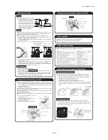
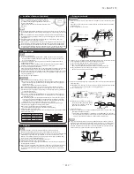
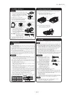
5. Fasten the hanging plate onto the suspension bolts.
6. Install the unit to the hanging plate.
(1)
Slide the unit in from front side to get it
hanged on the hanging plate with the bolts.
(2) Fasten the four fixing bolts (M8: 2
each on the left and right sides) firmly.
(3) Fasten the two screws (M4: 1 each on
the left and right sides).
WARNINIG
: Hang a side panel on from the
panel side to the rear side and
then fasten it securely onto
the indoor unit with screws.
̪
To ensure smooth drain flow, install the unit with
a descending slope toward the drain outlet.
CAUTION
: Do not give the reversed slope, which may cause water leaks.
⑥
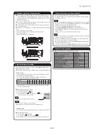
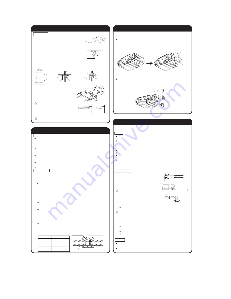
Refrigerant pipe
Pipe diameter
Tightening torque N·m
ø 6.35
ø 9.52
ø 12.7
ø 15.88
ø 19.05
14 to 18
34 to 42
49 to 61
68 to 82
100 to 120
Use the new refrigerant pipe.
When re-using the existing pipe system for R22 or R407C, pay attention to the following items.
Change the flare nuts with the attached ones (JIS category 2), and reprocess the flare parts.
Do not use thin-walled pipes.
Use phosphorus deoxidized copper alloy seamless pipe (C1220T specified in JIS H3300) for refrigeration pipe installation.
In addition, make sure there is no damage both inside and outside of the pipe, and no
harmful substances such as sulfur, oxide, dust or a contaminant stuck on the pipes.
Do not use any refrigerant other than R410A.
Using other refrigerant except R410A (R22 etc.) may degrade inside refrigeration oil. And air getting
into refrigeration circuit may cause over-pressure and resultant it may result in bursting, etc.
Store the copper pipes indoors and seal the both end of them until they are brazed in order to avoid any dust, dirt
or water getting into pipe. Otherwise it will cause degradation of refrigeration oil and compressor breakdown, etc.
Use special tools for R410 refrigerant.
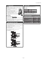
Work procedure
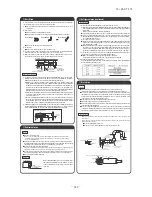
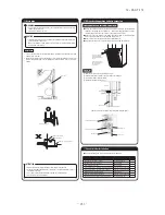
1. Remove the flare nut and blind flanges on the pipe of the indoor unit.
̪
Make sure to loosen the flare nut with holding the nut on pipe side with a spanner and giving torque to the
nut with another spanner in order to avoid unexpected stress to the copper pipe, and then remove them.
(Gas may come out at this time, but it is not abnormal.)
Pay attention whether the flare nut pops out. (as the indoor unit is sometimes pressured.)
2. Make a flare on liquid pipe and gas pipe, and connect the refrigeration pipes on the indoor unit.
When taking out the pipe to rear or top, install it together with the electric wire
⑧
,
passing them through the attached cover.
Seal clearances with putty, etc. to shut off dust.
̪
Bend the pipe with as big radius as possible and do not bend the pipe repeatedly.
In addition, do not twist and crush the pipes.
̪
Do a flare connection as follows:
Make sure to loosen the flare nut with holding the nut on pipe side with a spanner
and giving torque to the nut with another spanner in order to avoid unexpected
stress to the copper pipe, and then remove them.
When fastening the flare nut, align the refrigeration pipe with the center of flare nut, screw
the nut for 3-4 times by hand and then tighten it by spanner with the specified torque
mentioned in the table below. Make sure to hold the pipe on the indoor unit securely by a
spanner when tightening the nut in order to avoid unexpected stress on the copper pipe.
3. Cover the flare connection part of the indoor unit with attached insulation material
after a gas leakage inspection, and tighten both ends with attached straps.
Make sure to insulate both gas pipes and liquid pipes completely.
̪
Incomplete insulation may cause dew condensation or water dropping.
4. Refrigerant is charged in the outdoor unit.
As for the additional refrigerant charge for the indoor unit and piping, refer to the installation
manual attached to the outdoor unit.
Caution
⑦
Drain pipe
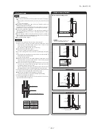
Work procedure
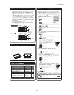
1. Insert drain hose completely to the
base, and tighten the drain hose clamp
securely. ( adhesive must not be used.)
̪
When plumbing on the left side, move the
rubber plug and the cylindrical insulating
materials by the pipe connecting hole on
the left side of the unit to the right side.
Beware of a possible outflow of water that may
occur upon removal of a drain plug.
2. Fix the drain hose at the lowest point with
a hose clamp supplied as an accessory.
̪
Give a drain hose a gradient of 10mm
as illustrated in the right drawing by
laying it without leaving a slack.
Take head of electrical cables so that
they may not run beneath the drain hose.
A drain hose must be clamped down with a hose clamp.
There is a possibility that drain water overflows.
3. Connect VP-20(prepare on site) to drain hose. (adhesive must not be used.)
̪
Use commercially available rigid PVC general pipe VP-20 for drain pipe.
4. Do not to make the up-down bending and trap in the mid-way while assum-
ing that the drain pipes is downhill. (more than 1/100)
Never set up air vent.
5. Insulate the drain pipe.
Insulate the drain hose clamp with the heat insulation supplied as accessories.
When the unit is installed in a humid place, consider precautions against
dew condensation such as heat insulation for the drain pipe.
Drain test
After installation of drain pipe, make sure that drain system work in good
condition and no water leakage from joint and drain pan.
Do drain test even if installation of heating season.
The drain pipes may face out towards the back to the left, or to the right side.
Caution
Install the drain pipe according to the installation manual in order to drain properly.
Imperfection in draining may cause flood indoors and wetting the household goods
etc.
Do not put the drain pipe directly into the ditch where toxic gas such as sulfur, the
other harmful and
inflammable gas is generated. Toxic gas would flow into the room and
it would cause serious damage to user’s health and safety (some poisoning or deficiency
of oxygen). In addition, it may cause corrosion of heat exchanger and bad smell.
Connect the pipe securely to avoid water leakage from the joint.
Insulate the pipe properly to avoid condensation drop.
Check if the water can flow out properly from both the drain outlet on the
indoor unit and the end of the drain pipe after installation.
Make sure to make descending slope of greater than 1/100 and do not make up-down bend and/or trap
in the midway. In addition, do not put air vent on the drain pipe. Check if water is drained out properly
from the pipe during commissioning. Also, keep sufficient space for inspection and maintenance.
⑥
Refrigerant pipe (continued)
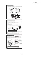
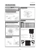
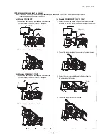
When the pipe is routed through the back.
If the bracket is removed, piping work will become easy.
̪
After piping, reinstall the removed bracket.
When the pipe is routed through the back.
Cut the removed top cover, and install to
the rear panel instead of rear cover.
Summary of Contents for FDC Series
Page 95: ... 94 12 PAC T 173 Models FDT100VF 125VF 140VF H H H H H C B A F G D G PJF000Z285 ...
Page 98: ... 97 12 PAC T 173 Models FDEN60VF 71VF C 2 C 1 A B A B D C 1 C 2 C 1 C 2 E G F B PFA003Z817 ...
Page 113: ... 112 12 PAC T 173 b Wireless remote controller RCN E1R 60 17 150 Unit mm ...
Page 278: ... 277 12 PAC T 173 ー K ...
Page 346: ... 345 12 PAC T 173 Power PCB 1BSU OVNCFS 4GRNCEG VJG 2 ...
Page 518: ... 517 12 PAC T 173 3 5 SUPER LINK E BOARD SC ADNA E F SL2NA E and SL3N AE BE to control ...
Page 519: ... 518 12 PAC T 173 ...

