-
223
-
'12 • PAC-T-173
Ԟ
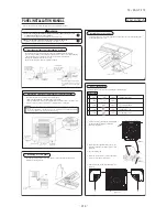
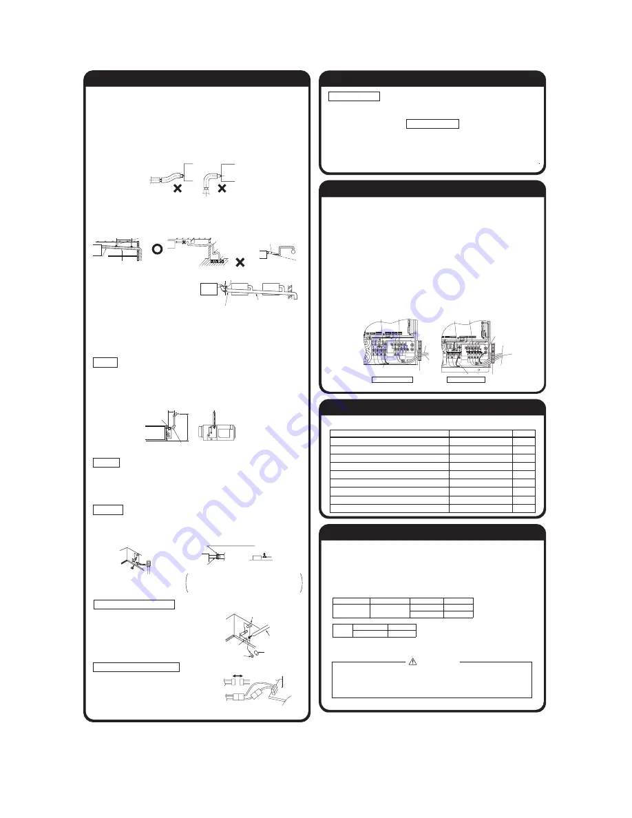
Drain pipe (continued)
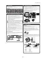
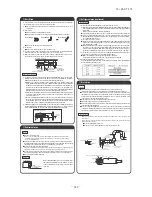
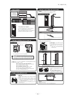
2. Prepare a joint for connecting VP-20 pipe, adhere and connect the joint to the drain hose
(the end made of rigid PVC), and adhere and connect VP-20 pipe (prepare on site).
̪
As for drain pipe, apply VP-20 made of rigid PVC which is on the market.
٨
When installing drain pipe, use VP-20 for the pipe goes up the closest to the unit, and
VP-25 or higher number product for farther pipes.
٨
Make sure that the adhesive will not get into the supplied drain hose.
It may cause the flexible part broken after the adhesive is dried up and gets rigid.
٨
The flexible drain hose is intended to absorb a small difference at installation of the unit
or drain pipes. Intentional bending, expanding may cause the flexible hose broken and
water leakage.
3. Make sure to make descending slope of greater than 1/100 and do not make up-down bend
and/or trap in the midway.
٨
Pay attention not to give stress on the pipe on the indoor unit side, and support and fix the
pipe as close place to the unit as possible when connecting the drain pipe.
٨
Do not set up air vent.
٨
When sharing a drain pipe for more than
one unit, lay the main pipe 100mm
below the drain outlet of the unit. In
addition, select VP-30 or bigger size for
main drain pipe.
Ԟ
Drain pipe (continued)
ԡ
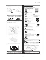
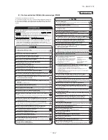
Tap selection on blower unit (when the high peformance filter is used)
ԟ
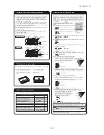
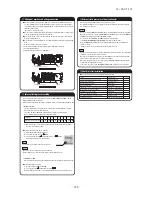
Wiring-out position and wiring connection
Ԡ
Check list after installation
Drain pump operation
٤
In case electrical wiring work finished
ޓ
Drain pump can be operated by remote controller (wired).
ޓ
For the operation method, refer to Operation for drain pump in the installation manual for wiring
work.
٤
In case electrical wiring work not finished
Drain pump will run continuously when the dip switch“SW7-1” on the indoor unit PCB is turned ON, the Connec-
tor CNB is disconnected, and then the power supply (230VAC on the terminal block
Ԙ
and
ԙ
) is turned ON.
Make sure to turn OFF “SW7-1” and reconnect the Connector CNB after the test.
٨
Electrical installation work must be performed according to the installation manual by an
electrical installation service provider qualified by a power provider of the country, and be
executed according to the technical standards and other regulations applicable to electrical
installation in the country.
Be sure to use an exclusive circuit.
٨
Use specified cord, fasten the wiring to the terminal securely, and hold the cord securely in
order not to apply unexpected stress on the terminal.
٨
Do not put both power source line and signal line on the same route. It may cause miscommu-
nication and malfunction.
٨
Be sure to do D type earth work.
٨
For the details of electrical wiring work, see attached instruction manual for electrical wiring
work.
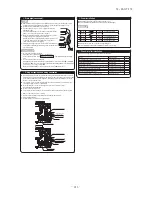
1. Remove a lid of the control box (2 screws).
2. Hold each wiring inside the unit and fasten them to terminal block securely.
3. Fix the wiring with clamps.
4. Install the removed parts back to original place.
The fan tap’s factory setting is “Standard.” If you want to change it to the high static-pressure setting,
you can avail yourself of the following two methods. Use one of the two methods to set the fan tap.
Make sure to perform the functional setting with remote controller.
Select [I/U FUNCTION] in the functional setting mode, and change the function number [02]
[FAN SPEED SET].
For operation method, refer to the user’s manual of the remote controller.
P.C. board
Fuse
For drain motor
connector CNR (blue)
Function number A Functional content B Setting content C Default setting
02
Fan Speed Set
Standard
٤
High Speed 1
Static
Pressure
Standard Tap
60
High Speed 1 Tap
130
UNIT: Pa
Insert water supply hose
for 50mm to
supply water.
(Insert hose facing
toward bottom.)
Attached drain hose clamp
Drain
piping
Main
unit
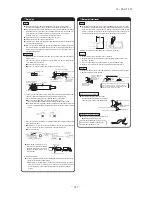
Drain situation can be checked with transparent socket.
If the electrical work has not been completed, connect a convex
joint in the drain pipe connection to provide a water inlet.
Then, check if water leaks from the piping system and that
drain flows through the drain pipe normally.
Pour water into a convex joint
Remove grommet
Make sure to Install
it back after test.
Connecting port of top drain pipe
Insulating material
Rubber stopper (to be removed)
Connecting port of bottom drain pipes
Standard hard polyvinyl
chloride pipes
(
)
٨
Check the following items after all installation work completed.
Check if
Expected trouble
Check
The indoor and outdoor units are fixed securely?
Falling, vibration, noise
Inspection for leakage is done?
Insufficient capacity
Insulation work is properly done?
Water leakage
Water is drained properly?
Water leakage
Supply voltage is same as mentioned in the model name plate? PCB burnt out, not working at all
There is mis-wiring or mis-connection of piping?
PCB burnt out, not working at all
Earth wiring is connected properly?
Electric shock
Cable size comply with specified size?
PCB burnt out, not working at all
Any obstacle blocks airflow on air inlet and outlet?
Insufficient capacity
Descending slope greater than 1/100
As wide as possible
(about100mm)
Insulation material
Supporting metal
Descending slope greater than 1/100
Air vent
No bump
No trap
Not touching the water
Trapped air will
generate noises.
VP-30 or bigger
1.5m~2m
Single unit wiring connection
Inner/outer
connecting line
Remote
controller line
Power source side
terminal block
Signal side
terminal block
Multi unit wiring connection
Superlynk line
(Shielded cord)
Earth
(Shielded cord)
Indoor power source line
Clamp for wiring at site
Clamp for wiring at site
Signal side
terminal block
Power source side
terminal block
Remote
controller line
Earth
Earth
CNS
CNV
CNT2
CNN
CNN
CNH
CNH
CNZ
CNA
CND
CNK2
CNR2
CNS
CNV
CNT2
CNN
CNH
CNZ
CNA
CND
C
NK2
C
NK1
CAUTION
If the external static pressure is 60Pa or less, do not set the fan speed to High speed 1.
If High speed 1 setting is done, air outlet speed from indoor unit will increase and
waterdrop may be blown out and wet the ceiling or the furniture.
290~325mm
Drain hose
600
Maximum local
drain up dimension
Joint for VP20 (local procurement)
Right overhead
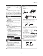
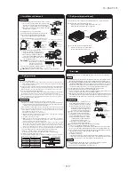
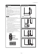
4. Insulate the drain pipe.
٨
Be sure to insulate the drain socket and rigid PVC pipe installed indoors otherwise it may
cause dew condensation and water leakage.
̪
After drainage test implementation, cover the drain socket part with pipe cover (small size), then
use the pipe cover (big size) to cover the pipe cover (small size), clamps and part of the drain
hose, and fix and wrap it with tapes to wrap and make joint part gapless.
Drain up
٨
The position for drain pipe outlet can be raised up to 600mm above the ceiling. Use elbows for
installation to avoid obstacles inside ceiling. If the horizontal drain pipe is too long before vertical pipe,
the backflow of water will increase when the unit is stopped, and it may cause overflow of water from the
drain pan on the indoor unit. In order to avoid overflow, keep the horizontal pipe length and offset of the
pipe within the limit shown in the figure below.
Otherwise, the construction point makes it same as drain pipe construction.
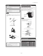
Drain test
1. Conduct a drain test after completion of the electrical work.
2. During the trail, make sure that drain flows properly through the piping and that no water
leaks from connections.
3. In case of a new building, conduct the test before it is furnished with the ceiling.
4. Be sure to conduct this test even when the unit is installed in the heating season.
Procedures
1. Supply about 1000 cc of water to the unit through the air outlet by using a feed water pump.
2. Check the drain while cooling operation.
Outline of bottom drain piping work
٨
If the bottom drain piping can be done with a
descending gradient (1/50-1/100), it is possible to
connect the pipes as shown in the drawing below.
Uncoupling the drain motor connector
٨
Uncouple the connector CNR for the drain motor
as illustrated in the drawing on the right.
Note: If the unit is run with the connector coupled,
drain water will be discharged from the upper drain
pipe joint, causing a water leak.
Summary of Contents for FDC Series
Page 95: ... 94 12 PAC T 173 Models FDT100VF 125VF 140VF H H H H H C B A F G D G PJF000Z285 ...
Page 98: ... 97 12 PAC T 173 Models FDEN60VF 71VF C 2 C 1 A B A B D C 1 C 2 C 1 C 2 E G F B PFA003Z817 ...
Page 113: ... 112 12 PAC T 173 b Wireless remote controller RCN E1R 60 17 150 Unit mm ...
Page 278: ... 277 12 PAC T 173 ー K ...
Page 346: ... 345 12 PAC T 173 Power PCB 1BSU OVNCFS 4GRNCEG VJG 2 ...
Page 518: ... 517 12 PAC T 173 3 5 SUPER LINK E BOARD SC ADNA E F SL2NA E and SL3N AE BE to control ...
Page 519: ... 518 12 PAC T 173 ...

