-
225
-
'12 • PAC-T-173
A
28
B
C
Ԛ
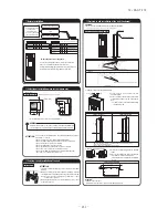
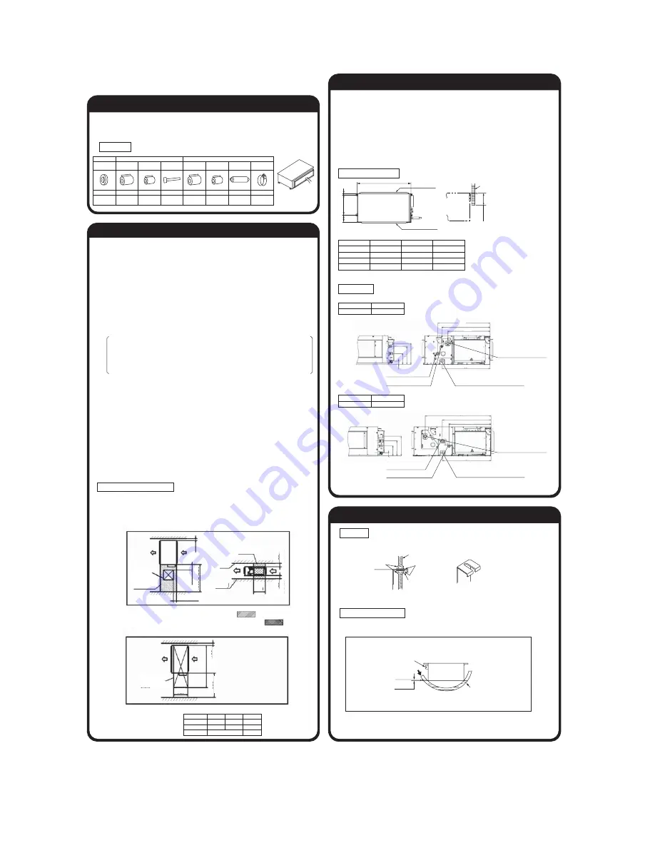
Preparation before installation
ԙ
Selection of installation location for the indoor unit
Ԙ
Select the suitable areas to install the unit under approval of the user.
ޓ
Areas where the indoor unit can deliver hot and cold wind sufficiently. Suggest to the user to use
a circulator if the ceiling height is over 3m to avoid warm air being accumulated on the ceiling.
Areas where there is enough space to install and service.
Areas where it can be drained properly. Areas where drain pipe descending slope can be
taken.
Areas where there is no obstruction of airflow on both air return grille and air supply port.
Areas where fire alarm will not be accidentally activated by the air conditioner.
Areas where the supply air does not short-circuit.
Areas where it is not influenced by draft air.
Areas not exposed to direct sunlight.
Areas where dew point is lower than around 28°C and relative humidity is lower than 80%.
This indoor unit is tested under the condition of JIS (Japan Industrial Standard) high humidity
condition and confirmed there is no problem. However, there is some risk of condensation
drop if the air conditioner is operated under the severer condition than mentioned above.
If there is a possibility to use it under such a condition, attach additional insulation of 10 to
20mm thick for entire surface of indoor unit, refrigeration pipe and drain pipe.
Areas where TV and radio stays away more than 1m. (It could cause jamming and noise.)
Areas where any items which will be damaged by getting wet are not placed such as food,
table wares, server, or medical equipment under the unit.
Areas where there is no influence by the heat which cookware generates.
Areas where not exposed to oil mist, powder and/or steam directly such as above fryer.
Areas where lighting device such as fluorescent light or incandescent light doesn’t affect
the operation.
(A beam from lighting device sometimes affects the infrared receiver for the wireless remote
controller and the air conditioner might not work properly.)
ԙ
Check if the place where the air conditioner is installed can hold the weight of the unit. If it is
not able to hold, reinforce the structure with boards and beams strong enough to hold it. If the
strength is not enough, it could cause injury due to unit falling.
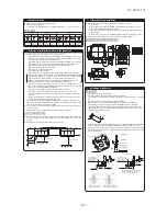
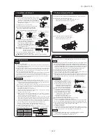
Space for installation and service
٨
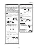
Make installation altitude over 2.5m.
(Indoor Unit)
Select either of two cases to keep space for installation and services.
Notes (a) There must not be obstacle to draw out fan motor. ( marked area)
(b) Install refrigerant pipe, drain pipe, and wiring so as not to cross marked area.
٨
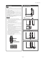
If suspension bolt becomes longer, do reinforcement of earthquake resistant.
ޓ٤
For grid ceiling
ޓޓ
When the suspension bolt length is over 500mm, or the gap between the ceiling and roof is
over 700mm, apply earthquake resistant brace to the bolt.
ޓ٤
In case the unit is hanged directly from the slab and is installed on the ceiling plane which
has enough strength.
ޓޓ
When suspension bolt length is over 1000mm, apply the earthquake resistant brace to the bolt.
٨
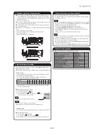
Prepare four (4) sets of suspension bolt, nut and spring washer (M10) on site.
٤
This model is middle static ducted type air conditioning unit. Therefore, do not use this model for direct
blow type air conditioning unit.
Suspension Bolt Location
٤
Adhere to the
measurements given
below for the length of
the suspension bolts.
Suspension
bolt (M10)
Return duct
Air supply duct
Unit
Under
60 mm
UNIT: mm
Multi type
Single type
A
B
C
22-56
50
786
472
135
71, 90
60, 71
986
472
135
112-160
100-140
1404
530
180
Installation
[Hanging]
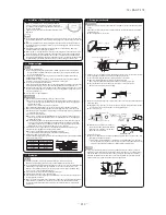
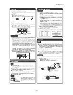
Hang the unit up.
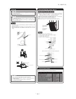
Adjustment for horizontality
٤
Either use a level vial, or adjust the level according to the method below.
٨
Adjust so the bottom side of the unit will be leveled with the water surface as
illustrated below.
٤
If the unit is not leveled, it may cause malfunctions or inoperation of the float switch.
Pipe side
Pour water
Water
surface
0~5mm
Vinyl hose
Let the pipe side be slightly sloped.
ԛ
Installation of indoor unit
M10 nut
Suspension bolt
Spring washer for M10
Unit
Washer for M10
If the measurements between
the unit and the ceiling hole do
not match upon installation, it
may be adjusted with the long
holed installation tool.
Multi type
Single type
112-160
100-140
Pipe locations UNIT: mm
Multi type
Single type
22-90
50-71
Ԙ
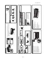
Before installation
٨
Install correctly according to the installation manual.
٨
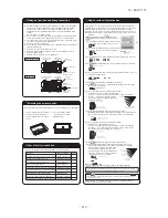
Confirm the following points:
ޓ٤
Unit type/Power supply specification
٤
Pipes/Wires/Small parts
٤
Accessory items
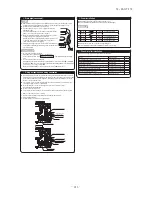
Accessory item
Accessory parts are stored
inside this suction side.
For refrigerant pipe
For drain pipe
Pipe cover (big) Pipe cover (small)
Pipe cover (big) Pipe cover (small)
Drain hose
Hose clamp
Strap
1
1
4
1
1
1
1
For heat insulation
of gas pipe
For heat insulation
of liquid tube
For pipe
cover fixing
For hanging
Flat washer (M10)
8
For unit
hanging
For drain hose
mounting
For heat insulation
of drain socket
For heat insulation
of drain socket
For drain pipe
connecting
Single type
Multi type
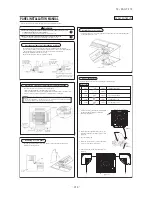
A
B
(Size of inspection hole)
50
22-56
1100
60-71
71-90
1300
100-140
112-160
1720
725
(For natural drainage)
drain pipe connection VP20 (PVC pipe)
drain pipe connection VP20
(PVC pipe)
510
635
468
405
467
187
145
95
29
471
413
203
174
104
29
467
Refrigerant liquid pipe
Refrigerant gas pipe
(For natural drainage)
drain pipe connection VP20 (PVC pipe)
drain pipe connection VP20
(PVC pipe)
Refrigerant gas pipe
Refrigerant liquid pipe
(Case 2) From bottom of unit
(Case 1) From side of unit
600
or more
100
or more
100
or more
20
or more
20
or more
A
B
Inspection
hole
Note (a)
Note (b)
100-200
370
150-
200
Ceiling
Slab
Inspection
hole
(450x450)
1000 or more
UNIT: mm
UNIT: mm
UNIT: mm
620
Summary of Contents for FDC Series
Page 95: ... 94 12 PAC T 173 Models FDT100VF 125VF 140VF H H H H H C B A F G D G PJF000Z285 ...
Page 98: ... 97 12 PAC T 173 Models FDEN60VF 71VF C 2 C 1 A B A B D C 1 C 2 C 1 C 2 E G F B PFA003Z817 ...
Page 113: ... 112 12 PAC T 173 b Wireless remote controller RCN E1R 60 17 150 Unit mm ...
Page 278: ... 277 12 PAC T 173 ー K ...
Page 346: ... 345 12 PAC T 173 Power PCB 1BSU OVNCFS 4GRNCEG VJG 2 ...
Page 518: ... 517 12 PAC T 173 3 5 SUPER LINK E BOARD SC ADNA E F SL2NA E and SL3N AE BE to control ...
Page 519: ... 518 12 PAC T 173 ...

