-
231
-
'12 • PAC-T-173
Ԙ
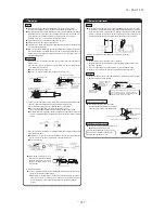
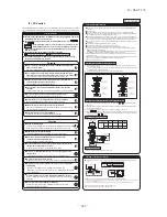
Before installation
ԙ
Selection of installation place for the indoor unit
Ԛ
Carrying-in and installation of the unit
Ԛ
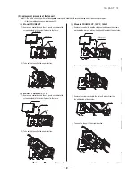
Carrying-in and installation of the unit (Continued)
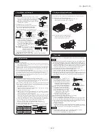
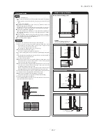
Ԙ
Loosen screws (2 pcs) and remove the fall-
prevention fitting.
ԙ
Select a position to fix the fall-prevention fitting
as illustrated and fix it to the top of unit and the
wall.
The fixing positon of the fall-prevention fitting
is as illastrated below.
Ԙ
Remove the L-fittings mounted on the unit with
screws.
ԙ
Turn over the L-fitting and fix it to the unit and
either the floor or the wall as illustrated.
Fixing position of the L-fittings are as illustrated
below.
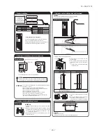
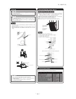
ATTENTION:
ATTENTION:
• Install the unit on the level.
Inclination must be less than 1°in fore-aft and right-left directions.
• Be sure to fix the unit with L-fittings and the fall-prevention fitting.
Fitting facing upward
Fitting facing downward
1815
〜
1840
25〜50
25〜50
1860
〜
1885
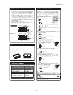
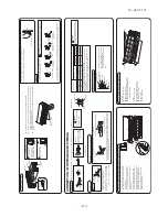
• Secure sufficient spaces for inspection and maintenance.
ATTENTION:
ATTENTION:
Model and power supply specification
Check.
(1)
For heat insulation of flare nut
1
Pipe cover
1 pc
For gas side
For liquid side
2
Pipe cover
1 pc
3
Strap
4 pcs
(2)
For installation
1
Fall-prevention fitting
Wood screw
Washer
Rubber bushing
L fitting
*3
For No. 1
For No. 2 wood screw
For refrigerant and drain pipes
*4
2
1 pc
2 pcs
2 pcs
1 pc
2 pcs
3
4
5
*3
*4
*1
、
2
(Indoor unit)
Note) Nos. 1 and 5 are used also as hardware for packing.
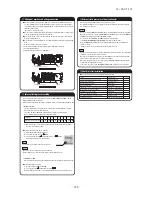
Installation space
Carrying-in
Minimum required spaces are shown as follows.
WARNING
Service
space
600
600
1000
100
50
Air outlet
Air inlet
(Unite: mm)
Carry with the front face at top.
50
Where the accessories are put in
Round head wood screw
Tapping screw
(Unit front)
Procedure for preventing the unit from falling
Fall-prevention fitting
Top panel
L fitting
*1
(1) Fixing the unit with the fall-prevention fitting
(2) Fixing the unit with the L-fittings
Fixing position (L fitting)
622.5
17.5
35
15
2×φ8
Fixing position (Fall-prevention fitting)
Since the unit is tall, secure the unit no sooner than setting it in place.
Pipes, wires and small parts
Accessory
*1. Open the air inlet grill and Nos. (1) will be found in the unit.
*2. Nos. (2)-2-4 will be found at the same place as 1.
*3. Fall-prevention fitting is mounting on the top panel of the unit.
*4. L-fittings are mounted on the bottom part of the unit.
• Install the unit securely on a floor that can endure its weight sufficiently Insuffi-
cient strength or incorrect installation could result in injuries if the unit falls.
Select a place for installation where the following conditions are fulfilled
with customer's consent.
• Where cool or hot air can be blown sufficiently and widely.
• Where the piping and wiring work to outdoor unit can be done easily.
• Where drainage water can run off completely.
• Where the installation floor is strong enough.
• Where the unit its protected from direct exposure to sunlight.
• Where there is no obstacle at he air inlet and air outlet.
• Where the fire alarm apparatus will not be activated by malfunction.
Where There is no risk for short-circuit of air.
• Carry in the unit kept in a package as near as possible to the installa-
tion place.
• When it is necessary to unpack the unit before carrying in, sufficient
care must be taken not to damage it by using nylon slings or the like.
Note) Do not hold on the air inlet grill, air outlet louver or other
sections made of plastics.
• When placing the unit on the floor after unpacking, be sure to have
its front face at the top.
Screw
Fall-prevention
fitting
For fixing to the wall
For securing the unit
• Dimensions indicate the allowance for adjustment between the unit and the wall or floor.
• Fix the longer side of fitting to the unit.
• When the fitting is faced downward, fix it to the wall first.
Mount the fall-prevention fitting at right or left position.
○
Install the unit properly
according to this
instruction manual.
○
Is it in accordance with
the construction plan?
Summary of Contents for FDC Series
Page 95: ... 94 12 PAC T 173 Models FDT100VF 125VF 140VF H H H H H C B A F G D G PJF000Z285 ...
Page 98: ... 97 12 PAC T 173 Models FDEN60VF 71VF C 2 C 1 A B A B D C 1 C 2 C 1 C 2 E G F B PFA003Z817 ...
Page 113: ... 112 12 PAC T 173 b Wireless remote controller RCN E1R 60 17 150 Unit mm ...
Page 278: ... 277 12 PAC T 173 ー K ...
Page 346: ... 345 12 PAC T 173 Power PCB 1BSU OVNCFS 4GRNCEG VJG 2 ...
Page 518: ... 517 12 PAC T 173 3 5 SUPER LINK E BOARD SC ADNA E F SL2NA E and SL3N AE BE to control ...
Page 519: ... 518 12 PAC T 173 ...


