-
246
-
'12 • PAC-T-173
Security instructions
CAUTION
WARNING
٨
٨
٨
٨
٨
٨
٨
Do not mingle solid cord and stranded cord on power source and signal side
terminal block.
In addition, do not mingle difference capacity solid or stranded cord.
Inappropriate cord setting could cause loosing screw on terminal block, bad electrical
contact, smoke and fire.
٨
٨
٨
٨
٨
٨
٨
٨
٨
٨
PGAO12D405
٨
٨
٨
٨
Electrical wiring work must be performed by an electrician qualified by a local power provider according to
the electrical installation technical standards and interior wiring regulations applicable to the installation site.
Be sure to have the electrical wiring work done by qualified electrical installer,
and use exclusive circuit.
Power source with insufficient capacity and improper work can cause electric shock and fire.
Use specified wire for electrical wiring, fasten the wiring to the terminal securely,
and hold the cable securely in order not to apply unexpected stress on the terminal.
Loose connections or hold could result in abnormal heat generation or fire.
Arrange the electrical wires in the control box properly to prevent them from
rising. Fit the lid of the services panel property.
Improper fitting may cause abnormal heat and fire.
Use the genuine optional parts. And installation should be performed by a
specialist.
If you install the unit by yourself, it could cause water leakage, electric shock and fire.
Turn off the power source during servicing or inspection work.
If the power is supplied during servicing or inspection work, it could cause electric
shock and injury by the operating fan.
Perform earth wiring surely.
Do not connect the earth wiring to the gas pipe, water pipe, lightning rod and telephone earth
wiring. Improper earth could cause unit failure and electric shock due to a short circuit.
Make sure to install earth leakage breaker on power source line.
(countermeasure thing to high harmonics.)
Absence of breaker could cause electric shock.
Do not use any materials other than a fuse of correct capacity where a fuse
should be used.
Connecting the circuit by wire or copper wire could cause unit failure and fire.
Do not turn off the power source immediately after stopping the operation.
Be sure to wait for more than 5 minutes. Otherwise it could cause water leakage or
breakdown.
Do not control the operation with the circuit breaker.
It could cause fire or water leakage. In addition, the fan may start operation
unexpectedly and it may cause injury.
Do not repair by yourself. And consult with the dealer about repair.
Improper repair may cause water leakage, electric shock or fire.
Consult the dealer or a specialist about removal of the air conditioner.
Improper installation may cause water leakage, electric shock or fire.
Shut off the power before electrical wiring work.
It could cause electric shock, unit failure and improper running.
Use the circuit breaker of correct capacity. Circuit breaker should be the one
that disconnect all poles under over current.
Using the incorrect one could cause the system failure and fire.
Earth leakage breaker must be installed.
If the earth leakage breaker is not installed, it can cause electric shocks.
Use power source line of correct capacity.
Using incorrect capacity one could cause electric leak, abnormal heat generation and fire.
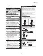
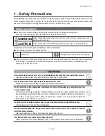
Read the “SAFETY PRECAUTIONS” carefully first of all and then strictly follow it during the
installation work in order to protect yourself.
The precautionary items mentioned below are distinguished into two levels,
and .
: Wrong installation would cause serious consequences such as injuries or death.
: Wrong installation might cause serious consequences depending on circumstances.
Both mentions the important items to protect your health and safety so strictly follow
them by any means.
The meanings of “Marks” used here are as shown on the right:
Accord with following items. Otherwise, there will be the risks of electric shock and
fire caused by overheating or short circuit.
Never do it under any circumstances.
CAUTION
CAUTION
Always do it according to the instruction.
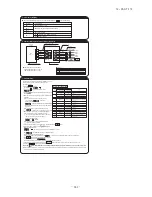
Electrical Wiring Connection
ԙ
Wiring for the remote controller
Power source
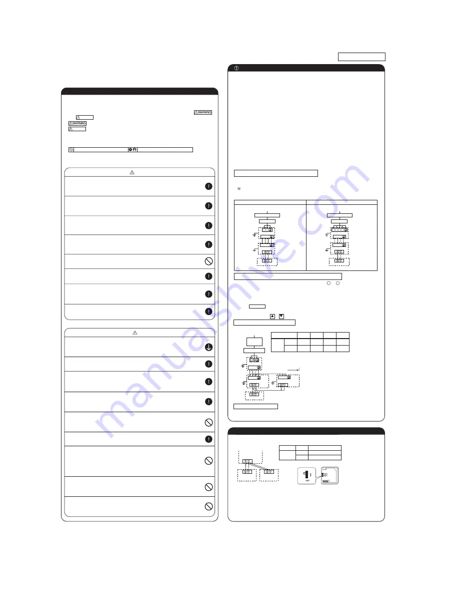
Cable connection for single unit installation
Cable connection for a V multi configuration installation
Three-phase model
Single-phase model
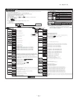
Method of setting Master/Slave of indoor unit
Switch and wiring specification
(Factory setting: “Master”)
Refer to the installation manual attached to the outdoor unit.
PCB
SW
SW5-1
OFF
OFF
OFF
ON
ON
ON
ON
OFF
SW5-2
㩷
㽲㽳㽴
㽲㽳㽴㩷 㩷 㩷 㩷 㩷 㩷 㩷
㽲㽳㽴㩷
㽲㽳㽴㩷
㪣㩷㩷㪥
Remote controller
Remote controller
Remote controller
controller line
Power source line
Indoor-Outdoor
Power source
Circuit breaker
Indoor Unit
Indoor Unit
Master
Slave 1
Slave 2
Slave 3
㽲㽳㽴㩷
㽲㽳㽴㩷
㪣㪈㩷㪣㪉㩷㪣㪊㩷㩷㪥
Master
Slave 1
Twin type
㽲㽳㽴
Remote controller line (no polarity)
AIR CON NO.
Outdoor Unit
Indoor Unit
Indoor Unit
Outdoor Unit
Indoor Unit
Outdoor Unit
Ea rth
Ea rth
Ea rth
Ea rth
Ea rth
Ea rth
Ea rth
Ea rth leakage
breaker
Power source
٨
Use three-core cable as wiring between indoor and outdoor unit. As for detail, refer to "INSTALLATION MANUAL" of
outdoor Unit.
٨
Set earth of D-type.
٨
Keep "remote controller line" and "power source line" away from each other on constructing of unit outside.
٨
Run the lines (power source, remote controller and "between indoor and outdoor unit") upper ceiling through iron
pipe or other tube protection to avoid the damage by mouse and so on.
٨
Do not add cord in the middle of line route (of power source, remote controller and "between indoor and outdoor
unit") on outside of unit. If connecting point is flooded, it could cause problem as for electric or communication. (In
the case that it is necessary to set connecting point on the way, perform thorough waterproof measurement.)
٨
Do not connect the power source line [220V/240V/380V/415V] to signal side terminal block. Otherwise, it could
cause failure.
٨
Screw the line to terminal block without any looseness, certainly.
٨
Do not turn on the switch of power source, before all of line work is done.
٨
Connection of the line ("Between indoor and outdoor unit", Earth and Remote controller)
Ԙ
Remove lid of control box before connect the above lines, and connect the lines to terminal block according to
number pointed on label of terminal block.
In addition, pay enough attention to confirm the number to lines, because there is electrical polarity except earth
line. Furthermore, connect earth line to earth position of terminal block of power source.
ԙ
Install earth leakage breaker on power source line. In addition, select the type of breaker for inverter circuit as
earth leakage breaker.
Ԛ
If the function of selected earth leakage breaker is only for earth-fault protection, hand switch (switch itself and
type "B" fuse) or circuit breaker is required in series with the earth leakage breaker.
ԛ
Install the local switch near the unit.
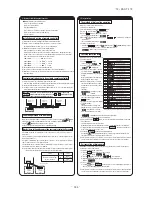
Ԙ
As for connecting method of power source, select from following connecting patterns. In principle, do not directly connect
power souce line to inside unit.
As for exceptional connecting method of power souce, discuss with the power provider of the country with referring to
technical documents, and follow its instruction.
ԙ
For cable size and circuit breaker selection, refer to the outdoor unit installation manual.
Ԙ
Connect the same pairs number of terminal block "
Ԙ
ԙ
and
Ԛ
"and " X and Y " between master and slave
indoor units.
ԙ
Do the same address setting of all inside units belong to same refrigerant system by rotary switch SW2 on indoor
unit's PCB (Printed circuit board).
Ԛ
Set slave indoor unit as "slave 1" through "slave 3" by address switch SW5-1, 5-2 on PCB.
ԛ
When the button on the remote control unit is pressed after turning on the power, an indoor unit's address
number will be displayed. Do not fail to confirm that the connected indoor unit's numbers are displayed on the remote
control unit by pressing the or button.
Circuit breaker
r
k
Circuit breaker
Ea rth leakage breaker
Connecting line
Remote
controller line
Power source line
Indoor-Outdoor
Connecting line
Remote
Earth leakage breaker
Earth leakage breaker
٨
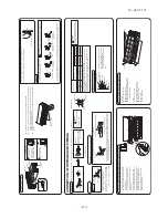
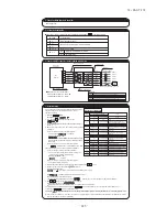
For each indoor unit, one more remote controller can be connected in addition to the one which is built in the main
unit.
Set SW1 to "Slave" for the slave remote controller. It was factory set to "Master" for shipment.
Note: The setting "Remote controller thermistor enabled" is only selectable with the master remote controller in the position where you
want to check room temperature.
The air conditioner operation follows the last operation of the remote controller regardless of the master/ slave setting of it.
Remote controller cord (no polarity)
Remote controller
SW1 "Master"
Switch
Setting
Contents
M
Master remote controller
SW1
S
Slave remote controller
Remote controller
SW1 "Slave"
Lower
Master
Slave
Upper
Board
Indoor units
* When setting the remote controller built in the main unit to the “Slave”:
Remove the cover and change the setting of switch as follows.
(3) FDF series
Summary of Contents for FDC Series
Page 95: ... 94 12 PAC T 173 Models FDT100VF 125VF 140VF H H H H H C B A F G D G PJF000Z285 ...
Page 98: ... 97 12 PAC T 173 Models FDEN60VF 71VF C 2 C 1 A B A B D C 1 C 2 C 1 C 2 E G F B PFA003Z817 ...
Page 113: ... 112 12 PAC T 173 b Wireless remote controller RCN E1R 60 17 150 Unit mm ...
Page 278: ... 277 12 PAC T 173 ー K ...
Page 346: ... 345 12 PAC T 173 Power PCB 1BSU OVNCFS 4GRNCEG VJG 2 ...
Page 518: ... 517 12 PAC T 173 3 5 SUPER LINK E BOARD SC ADNA E F SL2NA E and SL3N AE BE to control ...
Page 519: ... 518 12 PAC T 173 ...

