-
250
-
'12 • PAC-T-173
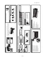
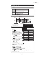
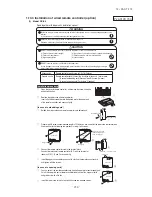
1.10.3 Installation of wired remote controller (option)
Read together with indoor unit's installation manual.
Accessories
Remote controller, wood screw (ø3.5
t
16) 2 pieces
Prepare on site
Remote controller cord (2 cores) the insulation thickness in 1mm or more.
[In case of embedding cord] Erectrical box, M4 screw (2 pieces)
[In case of exposing cord] Cord clamp (if needed)
Screw
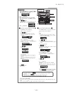
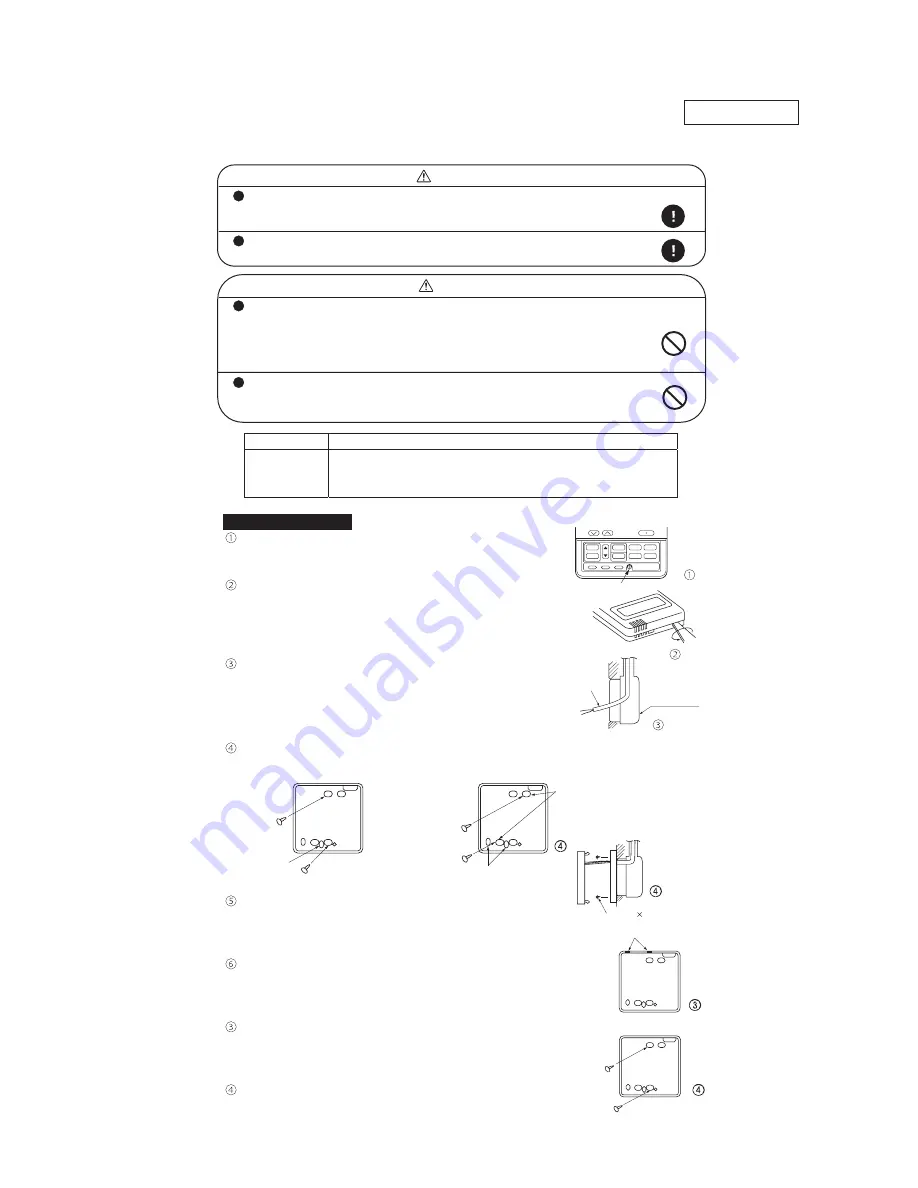
Installation procedure
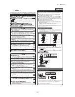
Open the cover of remote controller , and remove the screw under the
buttons without fail.
Remove the upper case of remote controller.
Insert a flat-blade screwdriver into the dented part of the upper part
of the remote controller, and wrench slightly.
[In case of embedding cord]
Embed the erectrical box and remote controller cord beforehand.
Prepare two M4 screws (recommended length is 12-16mm) on site, and install the lower case to erectrical box.
Choose either of the following two positions in fixing it with screws.
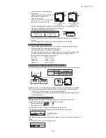
Connect the remote controller cord to the terminal block.
Connect the terminal of remote controller (X,Y) with the terminal of
indoor unit (X,Y). (X and Y are no polarity)
Install the upper case as before so as not to catch up the remote controller cord,
and tighten with the screws.
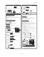
[In case of exposing cord]
You can pull out the remote controller cord from left upper part or center upper part.
Cut off the upper thin part of remote controller lower case with a nipper or knife,
and grind burrs with a file etc.
Install the lower case to the flat wall with attached two wooden screws.
WARNING
CAUTION
Fasten the wiring to the terminal securely and hold the cable securely so as not to apply unexpected stress on the
terminal.
Loose connection or hold will cause abnormal heat generation or fire.
Make sure the power supply is turned off when electric wiring work.
Otherwise, electric shock, malfunction and improper running may occur.
DO NOT install the remote controller at the following places in order to avoid malfunction.
DO NOT leave the remote controller without the upper case.
(1) Places exposed to direct sunlight
(2) Places near heat devices
(3) High humidity places
In case the upper cace needs to be detached, protect the remote controller with a packaging box or bag in
order to keep it away from water and dust.
(4) Hot surface or cold surface enough to generate condensation
(5) Places exposed to oil mist or steam directly
(6) Uneven surface
Tighten the screws after
cutting off the thin part of
screw mounting part.
Controller cord
Erectrical box
(Prepare on site)
Lower part
Lower part
Upper part
Lower case
Lower case
Wiring oulet
Wiring oulet
M4 screw 2 (Prepare on site)
The thin part
Upper part
Lower
Lower case
Upper
Lower
Lower case
Upper
PJA012D730
(1) Model RC-E5
Summary of Contents for FDC Series
Page 95: ... 94 12 PAC T 173 Models FDT100VF 125VF 140VF H H H H H C B A F G D G PJF000Z285 ...
Page 98: ... 97 12 PAC T 173 Models FDEN60VF 71VF C 2 C 1 A B A B D C 1 C 2 C 1 C 2 E G F B PFA003Z817 ...
Page 113: ... 112 12 PAC T 173 b Wireless remote controller RCN E1R 60 17 150 Unit mm ...
Page 278: ... 277 12 PAC T 173 ー K ...
Page 346: ... 345 12 PAC T 173 Power PCB 1BSU OVNCFS 4GRNCEG VJG 2 ...
Page 518: ... 517 12 PAC T 173 3 5 SUPER LINK E BOARD SC ADNA E F SL2NA E and SL3N AE BE to control ...
Page 519: ... 518 12 PAC T 173 ...

