-
259
-
'12 • PAC-T-173
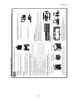
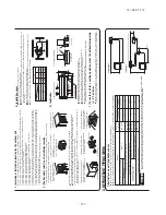
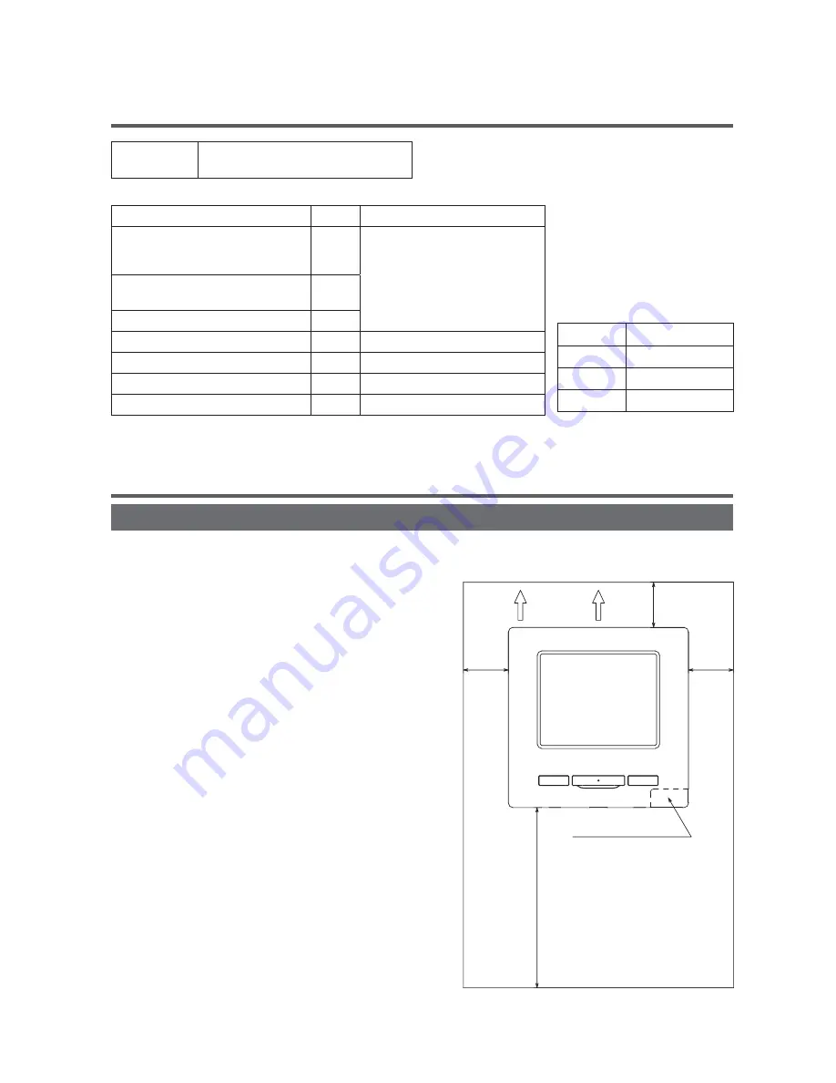
2 . Accessories & Prepare on site
Item name
Q’ty
Remark
Switch box
For 1 piece or 2 pieces (JIS C8340 or
equivalent)
1
These are not required when installing
directly on a wall.
Thin wall steel pipe for electric appliance
(JIS C8305 or equivalent)
As required
Lock nut, bushing (JIS C8330 or equivalent) As required
Lacing (JIS C8425 or equivalent)
As required Necessary to run R/C cable on the wall.
Putty
Suitably For sealing gaps
Molly anchor
As required
R/C cable (0.3 mm
2
x 2 pcs)
As required See right table when longer than 100 m
Accessories
R/C main unit, wood screw (ø3.5 x 16) 2 pcs
User’s Manual, Installation Manual
Parts procured at site
When the cable length is longer than
100 m, the max size for wires used
in the R/C case is 0.5 mm
2
. Connect
them to wires of larger size near
the outside of R/C. When wires are
connected, take measures to prevent
water, etc. from entering inside.
< 200 m
0.5 mm
2
x 2-core
< 300 m
0.75 mm
2
x 2-core
< 400 m
1.25 mm
2
x 2-core
< 600 m
2.0 mm
2
x 2-core
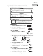
3. Remote control installation procedure
Determine where to install the remote control
Installation
“Using a switch box”
“Installed directly on a wall”
Wiring direction
“Backward”
“Upper center”, “Upper left”
Cautions for selecting installation place
(1) Installation surface must be flat and sufficiently strong.
R/C case must not be deformed.
(2) Where the R/C can detect room temperatures accurately.
This is a must when detecting room temperatures with
the temperature sensor of R/C.
· Install the R/C where it can detect the average tempera-
ture in the room.
· Install the R/C separated from a heat source sufficiently.
· Install the R/C where it will not be influenced by the
turbulence of air when the door is opened or closed.
Select a place where the R/C is not exposed to direct
sunlight or blown by winds from the air conditioner or
temperatures on the wall surface will not deviate largely
from actual room temperature.
Installation space
30mm
30mm
30mm
120mm
R/C temperature sensor
Wiring
Secure minimum spaces for
disassembling the case.
Upper left and Upper right sides
…
…
30mm or more
Bottom side…
120mm or more
If using L-shaped
screwdriver, 50mm or
more is available.
Summary of Contents for FDC Series
Page 95: ... 94 12 PAC T 173 Models FDT100VF 125VF 140VF H H H H H C B A F G D G PJF000Z285 ...
Page 98: ... 97 12 PAC T 173 Models FDEN60VF 71VF C 2 C 1 A B A B D C 1 C 2 C 1 C 2 E G F B PFA003Z817 ...
Page 113: ... 112 12 PAC T 173 b Wireless remote controller RCN E1R 60 17 150 Unit mm ...
Page 278: ... 277 12 PAC T 173 ー K ...
Page 346: ... 345 12 PAC T 173 Power PCB 1BSU OVNCFS 4GRNCEG VJG 2 ...
Page 518: ... 517 12 PAC T 173 3 5 SUPER LINK E BOARD SC ADNA E F SL2NA E and SL3N AE BE to control ...
Page 519: ... 518 12 PAC T 173 ...

