-
273
-
'12 • PAC-T-173
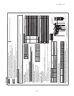
2.
REFRIGERANT PIPING WORK
C
AUTION
●
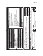
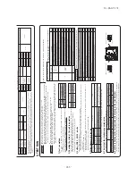
The use restrictions a
ppearing in the table above are a
pplicable to the standard pipe size combina
tions sho
wn in the table belo
w
.
Where an existing pipe system is utilized,
different one-way pipe length restrictions should a
pply depending on its pipe size.
F
or more informa
tion,
please see
“ 6.
UTIL
IZA
TION OF EXISTING PIPING.”
< Single type >
< T
win type >
Indoor unit (The unit of which eleva
tion difference from the outdoor unit is the largest.)
L1
L2
L (riser)
H
Outdoor unit
Indoor unit
h
L
H
Outdoor unit
Indoor unit
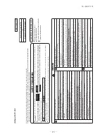
1) Restrictions on unit installation and use
●
Check the follo
wing points in light of the indoor unit specifica
tions and the installa
tion site.
●
Obser
ve the follo
wing restrictions on unit installa
tion and use.
Improper installa
tion can result in a compressor failure or p
erformance degrada
tion
.
2) Determination of pipe size
●
Determine
refrigerant
pipe
size
pursuant
to
the
follo
wing
guidelines
based
on
the
indoor
unit
specifica
tions
One-way pipe length of refrigerant piping
Restrictions
Dimensional
restrictions
Marks a
ppearing in the dra
wing on the right
50m or less
20m or less
10m or less
30m or less
15m or less
0.5m or less
L
L
−
−
H
H
−
L1
+
L1
+
L2
L
L1
,
L2
L1
−
L2
H
H
h
Eleva
tion difference between indoor units
Eleva
tion difference between
indoor and outdoor units
Model
71V
Difference of pipe length after the first branching point
One-way pipe length after the first branching point
Main pipe length
When the outdoor unit is positioned higher
,
When the outdoor unit is positioned lo
wer
,
Single type
Twin type
②
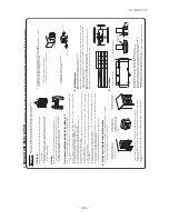
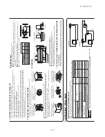
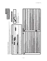
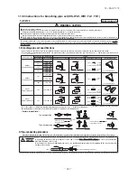
Notabilia for installa
tion
F
asten with bolts
(M10-12)
Use a thicker block to
anchor deeper
.
Use a long block to
extend the width.
①
Anchor bolt fixed position
●
In installing the unit,
fix the unit’
s legs with bolts specified on the above.
●
The protrusion of an anchor bolt on the front side must be kept within 15 mm.
●
Securely install the unit so tha
t it does not fall over during earthquakes or strong winds,
etc.
●
Refer to the above illustra
tions for informa
tion regarding concrete founda
tions.
●
Install the unit in a level area.
(With a gradient of 5 mm or less.)
Improper installa
tion can result in a compressor failure,
broken piping within the unit and abnormal noise genera
tion.
6) Installation
Intake
Anchor bolt position
Outlet
60
150
150
580
87.9
880
15
19
380
340
418
19
7) T
o
run the unit for a cooling operation,
when the outdoor temperature
is –5°C or lower
.
3) Selection of installation location for the outdoor unit
Be sure to select a suitable installa
tion place in considera
tion of follo
wing conditions.
〇
A place where it is horizontal,
stable and can endure the unit weight and will not allo
w vibra
tion transmittance of the unit.
〇
A place where it can be free from possibility of bothering neighbors due to noise or exhaust air from the unit
〇
A place where the unit is not exposed to oil splashes.
〇
A place where it can be free from danger of flammable gas leaka
ge.
〇
A place where drain wa
ter can be disposed without an
y trouble.
〇
A place where the unit will not be affected by hea
t radia
tion from other hea
t source.
〇
A place where sno
w will not accumula
te.
〇
A place where the unit can be kept a
way 5m or more from
TV set and/or radio receiver in order to a
void an
y radio or
TV interfer
ence.
〇
A place where good air circula
tion can be secured,
and enough ser
vice space can be secured for maintenance and ser
vice of the u
nit safely
.
〇
A place where the unit will not be affected by electroma
gnetic wa
ves and/or high-harmonic wa
ves genera
ted by other equipment.
〇
A place where chemical substances like sulfuric gas,
chloric gas,
acid and alkali (inc
luding ammonia),
which can harm the
unit,
will not be genera
ted and not remain.
〇
A place where strong wind will not blo
w a
gainst the outlet air blo
w of the unit.
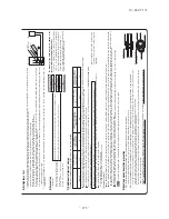
4) Caution about selection of installation location
(1) If the unit is installed in the area where the sno
w will accumula
te,
follo
wing measures are required.
The bottom pla
te of unit and intake,
outlet may be blocked by sno
w
.
3.
Install the unit under ea
ves
or provide the roof on site.
1.
Install the unit on the base so
tha
t the bottom is higher than
sno
w cover surface.
2.
Provide a sno
w hood to the outdoor
unit on site.
Regarding
outline
of
a
sno
w
hood,
refer to our technical manual.
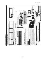
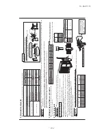
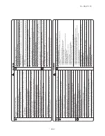
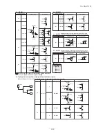
5) Installation space
●
W
alls surrounding the unit in the four sides are not acceptable.
●
There must be a 1-meter or larger space in the above.
●
When more than one unit are installed side by side, provide a 250mm or wider interval between them as a service space. In
order to facilitate servicing of controllers, please provide a sufficient space between units so that their top plates can be
removed easily.
●
Where a danger of short-circuiting exists,
install guide louvers.
●
When more than one unit are installed,
provide sufficient intake space consciously so tha
t short-circuiting may not occur
.
●
Where piling sno
w can bur
y the outdoor unit,
provide proper sno
w guards.
Intake
(
ser
vice
space
)
Intake
Outlet
L
3
L
2
L
4
L
1
71V
Example installa
tion
Size
L1
L2
L3
L4
Ⅰ
Open
300
100
250
Ⅱ
Open
250
150
250
Ⅲ
500
Open
100
250
(mm)
Wind direction
Wind direction
Over 500 mm
2.Install the outlet air blo
w side of
the unit in a position perpendicular
to the direction of wind.
1.Install the outlet air blo
w side of the
unit to face a wall of building,
or
provide a fence or a windbreak screen.
3.The unit should be installed on
the stable and level founda
tion.
If the founda
tion is not level,
tie do
wn the unit with wires.
Since drain wa
ter genera
ted by defrost control may freeze,
follo
wing measures are required.
●
Don’t execute drain piping work by using a drain elbo
w and drain grommets (optional parts).
[Refer to Drain piping work.]
●
Recommend setting Defrost Control (SW3-1) and Sno
w Guard F
an Control (SW3-2).
[Refer to Setting SW3-1,
SW3-2.]
(2) If the unit can be affected by strong wind,
follo
wing measures are required.
Strong wind can cause dama
ge of fan (fan motor),
or can cause performance degrada
tion,
or can trigger anomalous stop of
the unit due to rising of high pressure.
●
When the outdoor air tempera
ture is -5°C or lo
wer
, provide a sno
w hood to the outdoor unit on site.
So tha
t strong wind
will not blo
w a
gainst the outdoor hea
t exchanger directly
. Regarding outline of a sno
w hood,
refer to
our technical manual.
Summary of Contents for FDC Series
Page 95: ... 94 12 PAC T 173 Models FDT100VF 125VF 140VF H H H H H C B A F G D G PJF000Z285 ...
Page 98: ... 97 12 PAC T 173 Models FDEN60VF 71VF C 2 C 1 A B A B D C 1 C 2 C 1 C 2 E G F B PFA003Z817 ...
Page 113: ... 112 12 PAC T 173 b Wireless remote controller RCN E1R 60 17 150 Unit mm ...
Page 278: ... 277 12 PAC T 173 ー K ...
Page 346: ... 345 12 PAC T 173 Power PCB 1BSU OVNCFS 4GRNCEG VJG 2 ...
Page 518: ... 517 12 PAC T 173 3 5 SUPER LINK E BOARD SC ADNA E F SL2NA E and SL3N AE BE to control ...
Page 519: ... 518 12 PAC T 173 ...


