-
291
-
'12 • PAC-T-173
⑤
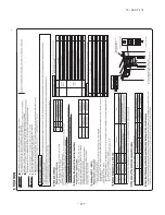
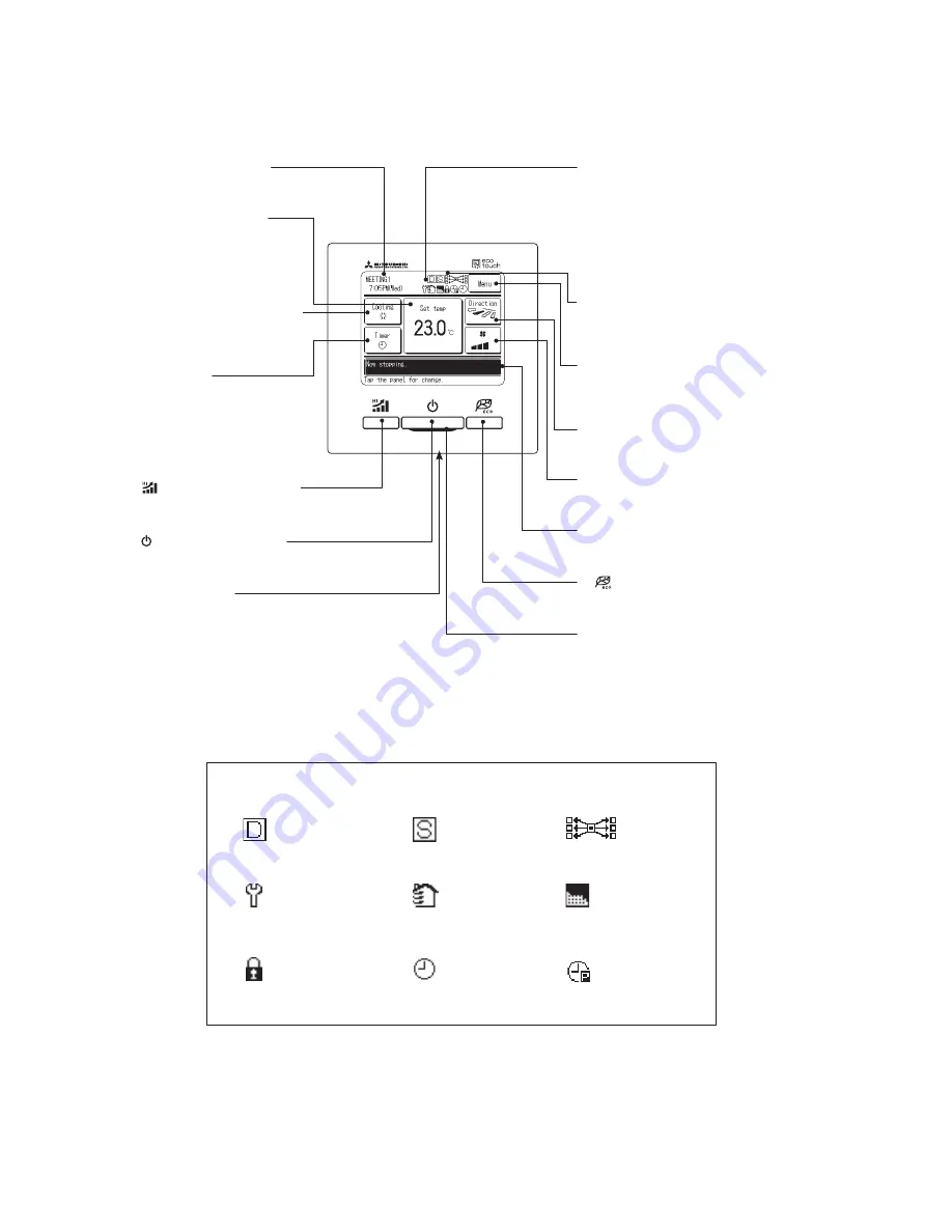
LCD display (With backlight)
④
Operation lamp
This lamp lights in green (yellow-green) during
operation. It changes to red if any error occurs.
⑥
USB port (mini-B)
USB connector (mini-B) allows connecting to a
personal computer.
For operating methods, refer to the instruction
manual attached to the software for personal
computer (eco-touch remote control RC-EX1,
utility software).
②
switch (High Power switch)
Pushing this button starts the high power
operation.
A tap on the LCD lights the backlight.
The backlight turns off automatically if there is no
operation for certain period of time.
Lighting period of the backlight lighting can be
changed.
If the backlight is ON setting, when the screen
is tapped while the backlight is turned off, the
backlight only is turned on.(Operations with
switches
①
,
②
and
③
are excluded.)
③
switch (Energy Saving switch)
Pushing this button starts the energy-saving
operation.
⑬
Fan speed change button
Displays the fan speed which is selected currently.
Tap this button to change the fan speed.
⑨
Menu button
When setting or changing other than the following
⑩
-
⑭
, tapthemenubutton.When menu items are
displayed, select one and set.
⑫
Flap direction button
Displays the flap direction which is selected currently.
Tap this button to change the flap direction.
⑦
Clock, R/C name display
Displays the current time and
the name of R/C
⑪
Change set temp button
Displays the temperature which
is set currently.Tap this button
to change the set temperature.
⑩
Change operation mode button
Displays the operation mode which
is selected currently. Tap this button
to change the operation mode.
⑭
Timer button
Displays simplified contents of the
timer which is set currently.
(When two or more timers are set,
contents of the timer which will be
operated immediately after is
displayed.)
Tap this button to set the timer.
①
switch (Run/Stop switch)
One push on the button starts operation
and another push stops operation.
⑧
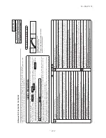
Icon display
Each icon is displayed when one of following settings
is going on.(It is referring to the following figure for
details.)
⑮
Message display
Status of air conditioner operation and messages of
the R/C operations etc.are displayed.
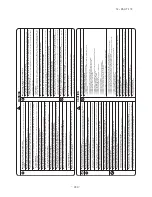
When the demand control
is effective.
When setting is made
from the sub R/C.
When the central control
(Optional) is running.
When the periodical
inspection is necessary.
During the ventilation
operation
When ”filter sign” is up.
When the Permission/
Prohibition setting is made.
When the peak-cut timer is set
When the weekly timer
is set.
⑧
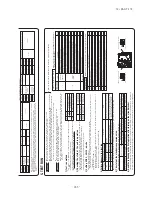
Icon display
Each icon is displayed when one of following settings is going on.
Touch panel system, which is operated by tapping the LCD screen with a finger, is employed for any operations
other than the
①
Run/Stop,
②
High power and
③
Energy-saving switches.
All icons are shown for the sake of explanation.
Model RC-EX1A
Summary of Contents for FDC Series
Page 95: ... 94 12 PAC T 173 Models FDT100VF 125VF 140VF H H H H H C B A F G D G PJF000Z285 ...
Page 98: ... 97 12 PAC T 173 Models FDEN60VF 71VF C 2 C 1 A B A B D C 1 C 2 C 1 C 2 E G F B PFA003Z817 ...
Page 113: ... 112 12 PAC T 173 b Wireless remote controller RCN E1R 60 17 150 Unit mm ...
Page 278: ... 277 12 PAC T 173 ー K ...
Page 346: ... 345 12 PAC T 173 Power PCB 1BSU OVNCFS 4GRNCEG VJG 2 ...
Page 518: ... 517 12 PAC T 173 3 5 SUPER LINK E BOARD SC ADNA E F SL2NA E and SL3N AE BE to control ...
Page 519: ... 518 12 PAC T 173 ...

