-
302
-
'12 • PAC-T-173
Stop
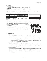
(1)
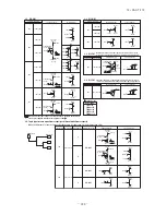
Indoor unit operation mode
Control A
Control B
Compressor ON
Compressor OFF
Cooling
Dehumidifying
Heating
Fan
(2)
Note (1) Including the stop from the cooling, dehumidifying, fan
and heating, and the anomalous stop
(2) Including the “Fan” operation according to the
mismatch of operation modes
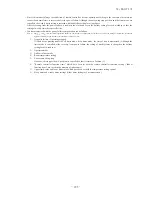
1)
Control A
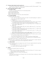
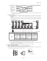
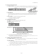
D ,IWKHÀRDWVZLWFKGHWHFWVDQ\DQRPDORXVGUDLQLQJFRQGLWLRQWKHXQLWVWRSVZLWKWKHDQRPDORXVVWRSGLVSOD\V(
and the drain pump starts. After detecting the anomalous condition, the drain motor continues to be ON.
E ,WNHHSVRSHUDWLQJZKLOHWKHÀRDWVZLWFKLVGHWHFWLQJWKHDQRPDORXVFRQGLWLRQ
2)
Control B
,I WKH ÀRDW VZLWFK GHWHFWV DQ\ DQRPDORXV GUDLQ FRQGLWLRQ WKH GUDLQ PRWRU LV WXUQHG 21 IRU PLQXWHV DQG DW
VHFRQGV DIWHU WKH GUDLQ PRWRU 2)) LW FKHFNV WKH ÀRDW VZLWFK ,I LW LV QRUPDO WKH XQLW LV VWRSSHG XQGHU WKH QRUPDO
mode or, if there is any anomalous condition, E9 is displayed and the drain motor is turned ON. (The ON condition is
maintained during the drain detection.)
(b)
Indoor unit performs the control A or B depending on each operating condition.
(13) Operation check/drain pump test run operation mode
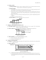
(a) If the power is turned on by the dip switch (SW7-1) on the indoor PCB when electric power source is supplied, it enters the
mode of operation check/drain pump test run. It is ineffective (prohibited) to change the switch after turning power on.
(b) When the communication with the remote controller has been established within 60 seconds after turning power on by the
dip switch (SW7-1) ON, it enters the operation check mode. Unless the remote controller communication is established, it
enters the drain pump test run mode.
Note (1) To select the drain pump test run mode, disconnect the remote controller connector (CNB) on the indoor PCB to shut down the remote controller
communication.
(c) Operation check mode
There is no communication with the outdoor unit but it allows performing operation in respective modes by operating the
remote controller.
(d) Drain pump test run mode
As the drain pump test run is established, the drain pump only operates and during the operation protective functions by
the microcomputer of indoor unit become ineffective.
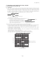
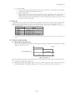
(14) Cooling, dehumidifying frost protection
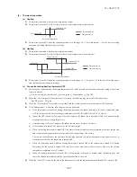
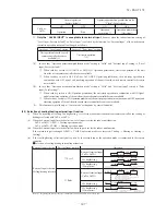
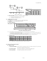
(a) To prevent frosting during cooling mode or dehumidifying mode operation, the of compressor speed is reduced if
the indoor heat exchanger temperature (detected with Th
I
-R) drops to 1.0 °C or lower at 4 minutes after the start of
compressor operation. If the indoor unit heat exchanger temperature is 1.0 °C or lower after 1 minutes, the compressor
speed is reduced further. If it becomes 2.5 °C or higher, the control terminates. When the indoor heat exchanger
temperature has become as show below after reducing the compressor speed, it is switched to the fan operation. For the
selection of indoor fan speed, refer to item 2).
10
1.0
Indoor heat exchanger temperature (°C)
Fan operation
Cooling operation
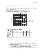
(b) Selection of indoor fan speed
If it enters the frost prevention control during cooling operation (excluding dehumidifying), the indoor unit fan speed is
switched.
1) When the indoor return air detection temperature (detected with Th
I
-A) is 23°C or higher and the indoor heat
exchanger temperature (detected with Th
I
-R) detects the compressor frequency drop start temperature A°C+1°C,
of indoor unit fan speed is increased by 20rpm.
2) If the phenomenon of 1) above is detected again after the acceleration of indoor unit fan, indoor unit fan speed
is increased further by 20rpm.
Note (1) Indoor unit fan speed can be increased by up to 2 taps.
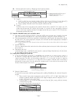
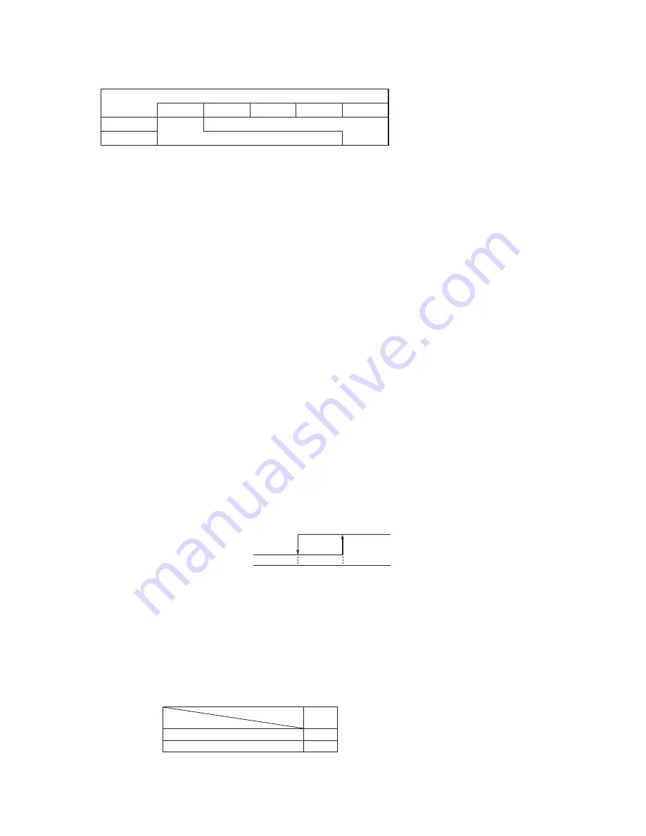
• Compressor frequency drop start temperature
Symbol
Item
A
Temperature - Low (Factory default)
1.0
Temperature - High
2.5
Note (1) Frost prevention temperature setting can be selected with the indoor unit function setting of the wired remote controller.
Summary of Contents for FDC Series
Page 95: ... 94 12 PAC T 173 Models FDT100VF 125VF 140VF H H H H H C B A F G D G PJF000Z285 ...
Page 98: ... 97 12 PAC T 173 Models FDEN60VF 71VF C 2 C 1 A B A B D C 1 C 2 C 1 C 2 E G F B PFA003Z817 ...
Page 113: ... 112 12 PAC T 173 b Wireless remote controller RCN E1R 60 17 150 Unit mm ...
Page 278: ... 277 12 PAC T 173 ー K ...
Page 346: ... 345 12 PAC T 173 Power PCB 1BSU OVNCFS 4GRNCEG VJG 2 ...
Page 518: ... 517 12 PAC T 173 3 5 SUPER LINK E BOARD SC ADNA E F SL2NA E and SL3N AE BE to control ...
Page 519: ... 518 12 PAC T 173 ...

