-
324
-
'12 • PAC-T-173
(5)
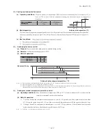
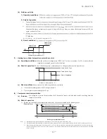
Defrosting
(a)
Defrosting start conditions
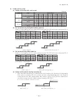
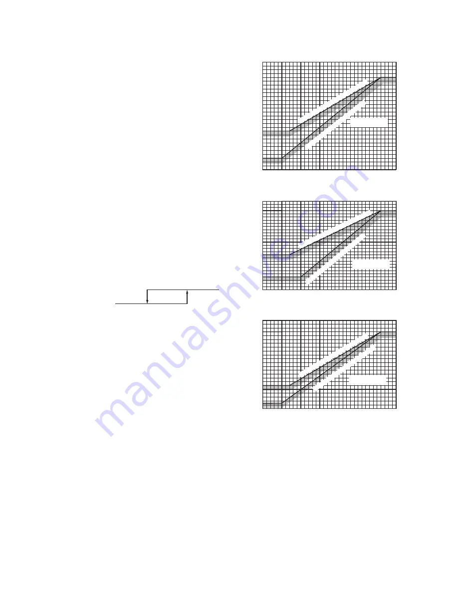
If all of the following defrosting conditions A or conditions
B are met, the defrosting operation starts.
1) Defrosting conditions A
a) Cumulative compressor operation time after the
end of defrosting has elapsed 37 [45] minutes,
and the cumulative compressor operation time
after the start of heating operation (remote
controller ON) has elapsed 30 minutes.
b) After 5 minutes from the compressor ON
c) After 5 minutes from the start of outdoor unit fan
d) After satisfying all above conditions, if temperatures
of the outdoor unit heat exchanger temperature
thermistor (Tho-R1, R2) and the outdoor air
temperature thermistor (Tho-A) become lower
than the defrosting start temperature as shown
by the right figure for 15 seconds continuously,
or the suction gas saturation temperature (SST)
and the outdoor air temperature (Tho-A), which
are obtained from the value detected by the
low pressure sensor (LPT) stay for 3 minutes
within the range below the defrosting operation
start temperature as shown by the right figure.
However, it excludes for 10 minutes after the start
of compressor and the outdoor air temperature is
as shown by the lower figure.
LPT detection
Outdoor air temp. (°C)
2
4
LPT invalid
Note (1) Figures in [ ] are for model 71.
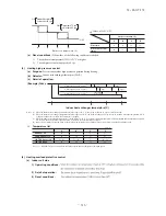
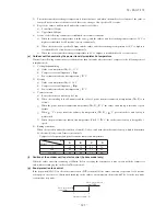
2) Defrosting conditions B
a) When previous defrosting end condition is
the time out of defrosting operation and it is
in the heating operation after the cumulative
compressor operation time after the end of
defrosting has become 30 minutes.
b) After 5 minutes from the start of compressor
c) After 5 minutes from the start of outdoor unit fan
(b)
Defrosting end conditions
When any of the following conditions is satisfied, the
defrosting end operation starts.
1) When it has elapsed 8 minutes and 20 seconds after the start of defrosting. (After 10 minutes and 20 seconds for
model 71)
2) When the outdoor unit heat exchanger temperatures (Tho-R1, R2), whichever the lower, becomes 12°C or higher for
10 seconds continuously.
Outdoor air temp.
(
͠
)
㨇
Tho-A
㨉
Outdoor air temp.
(
͠
)
㨇
Tho-A
㨉
Suction saturatio
n temp.
(
͠
)
㨇
SST
㨉
Suction saturatio
n temp.
(
͠
)
㨇
SST
㨉
-20
-25
-28.6
-30
-24
-15
-10
-8
-15
-10
-5
0
5 6
10
-20
-25
Defrost operation star
t temperature (Standard)
Defrost opera
tion st
art temperatu
re (SW
3-1 ON
)
-20
-25
-30
-31
-24
-15
-10
-8
-35
-15
-18
-10
-5
0
5 6
10
-25
-20
-18
Defrost
operation start temperature
(SW3-1 ON)
Defrost oper
ation start temperature
(Standard)
Defrost operation start
temperature zone
Defrost operation start
temperature zone
Model 71
Model 100-140
Outdoor air temp. (
͠
)
㨇
Tho-A
㨉
-20
-25
-27
-30
-15
-10
-5
-6
-2
-15
-10
-5
0
5 6
10
-20
-25
Defrost operation start
temperature zone
Defrost
operation start tem
perature
(Standard)
Defrost operation start
tem
perature (SW3-1
ON
)
Outdoor unit heat exchanger temp.
(
͠
)
㨇
Tho-R
㨉
-18
Model 71-140
Summary of Contents for FDC Series
Page 95: ... 94 12 PAC T 173 Models FDT100VF 125VF 140VF H H H H H C B A F G D G PJF000Z285 ...
Page 98: ... 97 12 PAC T 173 Models FDEN60VF 71VF C 2 C 1 A B A B D C 1 C 2 C 1 C 2 E G F B PFA003Z817 ...
Page 113: ... 112 12 PAC T 173 b Wireless remote controller RCN E1R 60 17 150 Unit mm ...
Page 278: ... 277 12 PAC T 173 ー K ...
Page 346: ... 345 12 PAC T 173 Power PCB 1BSU OVNCFS 4GRNCEG VJG 2 ...
Page 518: ... 517 12 PAC T 173 3 5 SUPER LINK E BOARD SC ADNA E F SL2NA E and SL3N AE BE to control ...
Page 519: ... 518 12 PAC T 173 ...

