-
329
-
'12 • PAC-T-173
(7)
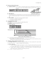
Silent mode
(a) As “Silent mode start” signal is received from the remote controller, it operates by dropping the outdoor unit fan tap and
the compressor speed (frequency).
(b) For details, refer to items (1) and (4) above.
(8)
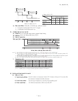
Test run
(a)
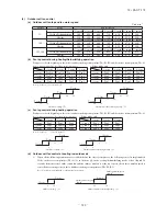
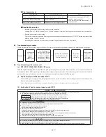
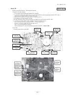
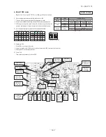
It is possible to operate from the outdoor unit using the dip switch on the outdoor unit control PCB.
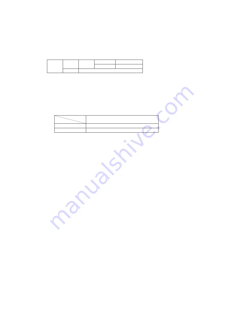
SW3-3
(SW5-3)
ON
SW3-4
(SW5-4)
OFF
Cooling test run
ON
Heating test run
OFF
Normal and end of test run
Make sure to turn SW3-3 (SW5-3) to OFF after the end of operation.
Note (1) Value in (
) is for the model 71.
(b)
Test run control
1) Operation is performed at the maximum compressor speed (frequency), which is determined for each model.
2) Each protective control and error detection control are effective.
3) If SW3-4 (SW5-4) is switched during test run, the compressor is stoped for once by the stop control and the cooling/
heating operation is switched.
Note (1) Value in (
) is for the model 71.
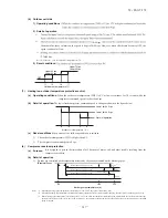
4) Setting and display of remote controller during test run
Item
Mode
Contents of remote controller setting/display
Cooling test run
Setting temperature of cooling is 5°C.
Heating test run
Setting temperature of heating (preparation) is 30°C.
(9)
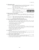
Pump-down control
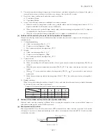
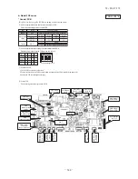
Turning ON the pump-down switch SW1 (SW9) for 2 seconds during the operation stop or anomalous stop (excluding the
thermostat OFF), the pump-down operation is performed. (This is invalid when the indoor unit is operating. This is effective
even when the indoor unit is stopped by the anomalous stop or the power supply is turned OFF.)
Note (1) Value in (
) are for the model 71.
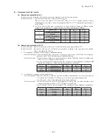
(a)
Control contents
1) Close the service valve at the liquid side. (It is left open at the gas side.)
2) Compressor is started with the target speed (frequency) at 71:62, 100:55, 125
・
140:45 rps in the cooling mode.
3) Red and green lamps (LED) flash continuously on the outdoor unit control PCB.
4) Each of protection and error detection controls, excluding the low pressure control, anti-frost control and dewing
prevention control, is effective.
5) Outdoor unit fan is controlled as usual.
6) Electronic expansion valve is fully opened.
(b)
Control ending conditions
Stop control is initiated depending on any of the following conditions.
1) Low pressure of 0.087MPa or lower is detected for 5 seconds continuously.
a) Red LED: Light, Green LED: Flashing, Remote controller: Displays stop.
b) It is possible to restart when the low pressure is 0.087MPa or higher.
c) Electronic expansion valve (cooling/heating) is kept fully open.
2) Stop by the error detection control
a) Red LED: Flashing, Green LED: Flashing
b) Restart is prohibited. To return to normal operation, reset the power supply.
c) Electronic expansion valve (cooling/heating) is left fully open.
3) When the cumulative operation time of compressor under the pump-down control becomes 5 minutes.
a) Red LED: OFF, Green LED: Flashing, Remote controller: Stop
b) It is possible to pump-down again.
c) Electronic expansion valve (cooling/heating) is left fully open.
Note (1) After the stop of compressor, close the service valve at the gas side.
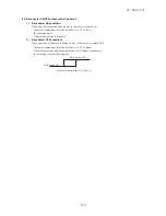
Caution: Since pressing the pump-down switch cancels communications with the indoor unit, the indoor unit and the
remote controller display “Transmission error – E5”. This is normal.
Summary of Contents for FDC Series
Page 95: ... 94 12 PAC T 173 Models FDT100VF 125VF 140VF H H H H H C B A F G D G PJF000Z285 ...
Page 98: ... 97 12 PAC T 173 Models FDEN60VF 71VF C 2 C 1 A B A B D C 1 C 2 C 1 C 2 E G F B PFA003Z817 ...
Page 113: ... 112 12 PAC T 173 b Wireless remote controller RCN E1R 60 17 150 Unit mm ...
Page 278: ... 277 12 PAC T 173 ー K ...
Page 346: ... 345 12 PAC T 173 Power PCB 1BSU OVNCFS 4GRNCEG VJG 2 ...
Page 518: ... 517 12 PAC T 173 3 5 SUPER LINK E BOARD SC ADNA E F SL2NA E and SL3N AE BE to control ...
Page 519: ... 518 12 PAC T 173 ...

