-
341
-
'12 • PAC-T-173
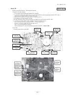
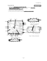
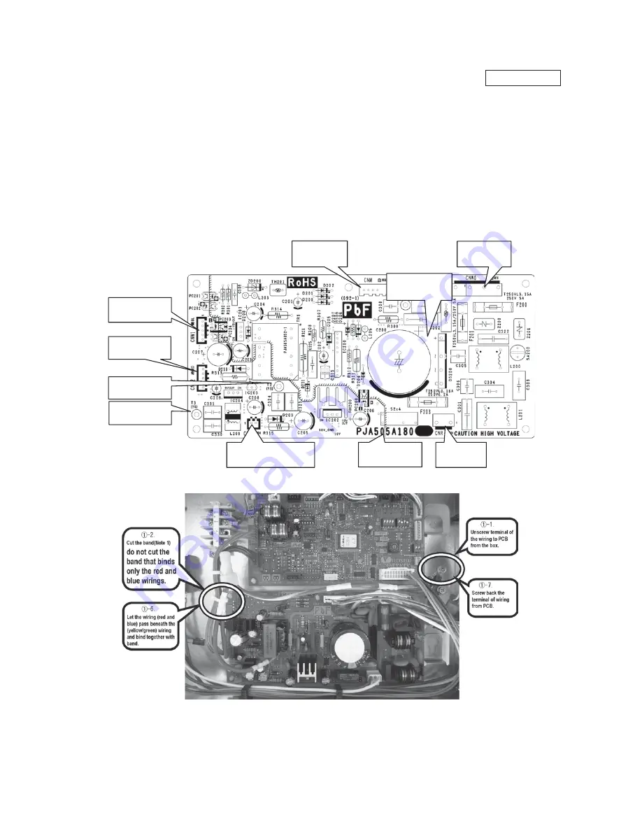
This PCB is a general PCB. Replace the PCB according to this instruction.
Ԙ
Replace the PCB (refer to right dwg.)
1. Unscrew terminal of the wiring(yellow/green) soldered to PCB from the box.
2. Cut the band that binds the wiring (red and blue) from connector CNW1 and CNW2, and the wiring (yellow/green) from PCB (T2/T3) . (Note 1)
(However, do not cut the band that binds only the red and blue wirings.)
3. Replace the PCB only after all the wirings connected to the connector are removed.
4. Fix the board such that it will not pinch any of the wires.
5. Reconnect the wirings to the PCB. Wiring connector color should match with the color of connector of the PCB. (Note 2)
6. Let the wiring (red and blue) pass beneath the (yellow/green) wiring and bind together with band.
7. Screw back the terminal of wiring (yellow/green) from PCB(T1
䋬
T2/T3), that was removed in 1.
In that case, do not place the crimping part of the wiring under the PCB.
(Note 1): It might not be applicable on some models.
(Note 2): After replacing PCB, connection between capacitor assy and connector CNP is
㵘
㵘
㵘
ԙ
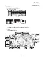
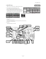
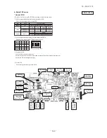
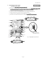
Power PCB
Parts mounting are different by the kind of PCB.
㪧㪸㫉㫋㩷㫅㫌㫄㪹㪼㫉
㪚㪥㪩䋨㪮㪿㫀㫋㪼䋩
㪛㫉㪸㫀㫅㩷㫄㫆㫋㫆㫉
㪚㪥㪮㪉㩿㪩㪼㪻䋩
㪚㫆㫅㫋㫉㫆㫃㩷㪧㪚㪙
㪚㪥㪤㩿㪮㪿㫀㫋㪼䋩
㪝㪸㫅㩷㫄㫆㫋㫆㫉
㪚㪥㪮㪈㩿㪙㫃㫌㪼䋩
㪚㫆㫅㫋㫉㫆㫃㩷㪧㪚㪙
㪚㪥㪮㪇䋨㪮㪿㫀㫋㪼䋩
㪫㪼㫉㫄㫀㫅㪸㫃㩷㪹㫃㫆㪺㫂
㩿㪥㫆㫋㪼㩷㪉㪀㩷㪚㪥㪧㩿㪮㪿㫀㫋㪼㪀
㪚㪸㫇㪸㪺㫀㫋㫆㫉㩷㪸㫊㫊㫐
㪫㪉㩿㪰㪼㫃㫃㫆㫎㪆㪞㫉㪼㪼㫅䋩
㪜㪸㫉㫋㪿
㪫㪊㩿㪰㪼㫃㫃㫆㫎㪆㪞㫉㪼㪼㫅䋩
㪜㪸㫉㫋㪿
䌔䋱㩿㪰㪼㫃㫃㫆㫎㪆㪞㫉㪼㪼㫅䋩
㪜㪸㫉㫋㪿
no longer needed.
PSB012D953A
•
Power PCB
Summary of Contents for FDC Series
Page 95: ... 94 12 PAC T 173 Models FDT100VF 125VF 140VF H H H H H C B A F G D G PJF000Z285 ...
Page 98: ... 97 12 PAC T 173 Models FDEN60VF 71VF C 2 C 1 A B A B D C 1 C 2 C 1 C 2 E G F B PFA003Z817 ...
Page 113: ... 112 12 PAC T 173 b Wireless remote controller RCN E1R 60 17 150 Unit mm ...
Page 278: ... 277 12 PAC T 173 ー K ...
Page 346: ... 345 12 PAC T 173 Power PCB 1BSU OVNCFS 4GRNCEG VJG 2 ...
Page 518: ... 517 12 PAC T 173 3 5 SUPER LINK E BOARD SC ADNA E F SL2NA E and SL3N AE BE to control ...
Page 519: ... 518 12 PAC T 173 ...


